WindWizard
Solar Enthusiast
The voltages are stored in memory. It may look like they are occurring at the same time but they are really not.I can still see the cell voltage even when the BMS is balancing my cells, did I buy special BMS


The voltages are stored in memory. It may look like they are occurring at the same time but they are really not.I can still see the cell voltage even when the BMS is balancing my cells, did I buy special BMS
I do accept the possibility of WindWizards (subsequent) explanation that balancing and voltage reading are not done at the same time. I think it would be easy to test with the right equipment (not sure if a simple DC clamp meter is good enough/fast enough).Sorry, plain wrong.
WindWizard has a big system that sounds like it is working well (great, nice work!) but i am not so willing to accept that the BMS has to work as he describes for his system to work.Absolutely!!!!!! Otherwise my system would not work with balance leads of 6 inches to 10 feet.
Agreed 100%Now if you were the design engineer for a BMS would you want it measuring voltage when you were drawing current out of a balance lead? The answer of course is no because the voltage would not be accurate.
In my opinion you have one of the best bms’s on the market. With a reasonably well matched set of cells that 2amp balance should be able to do the job but it could take a while the first time charging. You may need to greatly reduce the charge current once it starts to disconnect to give the balancer the time it needs to work. The default voltage when balancing starts is usually 3.4 volts, so you need to get it there for the magic to happen or temporarily reduce that setting if you’re having problems getting there because of a high cell voltage protection (3.65). If that’s triggered,the charging will disconnect but balancing will continue as long as you are also within the balance voltage range. The app will tell you if it’s balancing if by looking at the balance current, on some JK’s the “Balance On” just means it’s enabled, not active. There will be a yellow notification letting you know about the disconnect. I try to avoid the disconnect by lowering the charge and giving it time. I sometimes manually augment the process but that’s a whole other story. Yes, hwse is on the right track.Thanks for explaining this. I'm building my first LiFePO4 24 V pack from 8x EVE 280Ah cells, and I'm using a JK B2A8S20P BMS. Actually I'm building two such packs to run in parallel. Now I'm trying to decide if I'm going to top charge before I assemble the packs so the cells get off to a good start, or just ignore it and let the BMS sort it out over time. The cells are supposed to be matched in IR and capacity, and also in the same SOC when they are shipped (Luyuan shop). But you'll never know what shape the cells actually arrive in.
In your earlier post you gave the tip to set the charger to 13.6V (3.4 V/cell), do a full charge then let the BMS take a few hours to balance out the cells, then repeat the following days and each day increase the charger voltage in 0.1V steps (0.025V/cell). If I top balance at 3.55V, then it would take 6 days. At that point you can set the charger back to what ever normal voltage you use. Did I get that right? Sounds logical to me.
The only scenario I would suspect it doesn't work is if the BMS needs a very long time (days/weeks) to figure out the actual capacity and IR of each cell. Then it would do a poor job initially. People who don't top balance and use active BMS'es, what experience do they have?
Please correct me if I'm wrong, but on some level I don't see the point with top balancing, unless it is super important that the pack is optimized for max capacity from day one. The BMS will eventually make it optimized, and the cells will not get damaged in the process. I suspect that it is important to allow the pack to really get up to 100% charge every time (not limit it to 90% or less) during this process, because that's where the SOC/voltage curve really takes off so the SOC is easier to read for the BMS. So first a few weeks/month of balancing, then set the charger to whatever voltage/profile you want long term.
Thoughts?
I can see the voltage being pulled lower when I sell is being balanced, are you really going to make me make a video of this showing you. It's real I promise you.The voltages are stored in memory. It may look like they are occurring at the same time but they are really not.
No need for a video. You can see the Cell voltage pulled lower. If it balances like my Overkill then it balances a group of Cells. If the Cell voltage pops backup again when it goes to the next group then I would concede that it is using the voltage while pulling current. If it just goes down then I would be inclined to say it is measuring and storing the values and then using the stored values to determine which Cell needs to be balanced and is alternating between measuring and balancing or somehow doing a calculation based on wire resistance and then displaying the correct voltage.I can see the voltage being pulled lower when I sell is being balanced, are you really going to make me make a video of this showing you. It's real I promise you.
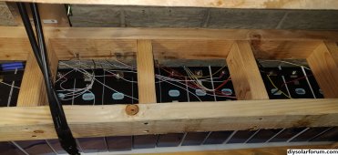
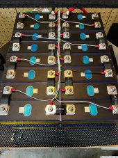
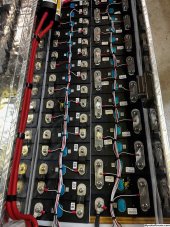
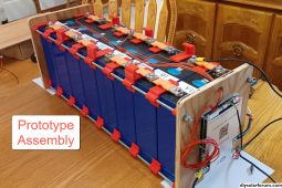
Very nicely done. Your wires are dressed very well. The only thing I do not like is putting your BMS wires under the Busbar nuts. I prefer drilling a hole in the busbar and attaching the BMS leads there. Just a personal preference and it probably does not make a difference. My thought pattern on this is it could add some resistance in connecting the Cells together. I purchased a torque wrench and torqued all my busbar nuts all to spec.I've always dressed out the BMS leads. No problems.
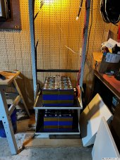
If you look at the second picture, the battery on the right, I drilled and tapped the bus bars. There was no discernible difference. That was my first set of cells and they came with the rigid bus bars. Subsequent cell purchase came with the semi flexible bus bars and I prefer them so I’ll be replacing everything with those on my new build. I have two shelves done and when complete, the rack will have four identical shelves.Very nicely done. Your wires are dressed very well. The only thing I do not like is putting your BMS wires under the Busbar nuts. I prefer drilling a hole in the busbar and attaching the BMS leads there. Just a personal preference and it probably does not make a difference. My thought pattern on this is it could add some resistance in connecting the Cells together. I purchased a torque wrench and torqued all my busbar nuts all to spec.
Not really. Just set it to whatever charge parameters you like best and let it work. It will take a bit longer, but it will still get the job done. In the meantime, there is no problem with the cells being out of balance other than that they will not have quite as much capacity as they could.I like to compress cells and don’t like to disassemble them once they are charged, so since I don’t use diagonal cable jumpers/busses for future builds, I now only use flexible buss bars. So the JK is the future balance from now on, preferably with time to do it. You got to be around to set the charger/system back to normal when it’s done.
In my opinion, some of your ideas are correct and some not so much. As far as how I top balance, you have it right except that after you get the pack balanced at 13.6v it will not take days, it will take minutes to get to each new high point. By the time you get all cells to 3.45v, you are at 98%-99% SOC and pretty well balanced. It is getting to 13.6v that can take a long time. The reason I choose 12.6v is because it is low enough to let the charger run but limit the charge current without tripping any of the cells for over voltage (OVP). If you have really badly out of balance cells, and the BMS triggers an OVP, lower the CV setpoint so that it will charge without tripping.Thanks for explaining this. I'm building my first LiFePO4 24 V pack from 8x EVE 280Ah cells, and I'm using a JK B2A8S20P BMS. Actually I'm building two such packs to run in parallel. Now I'm trying to decide if I'm going to top charge before I assemble the packs so the cells get off to a good start, or just ignore it and let the BMS sort it out over time. The cells are supposed to be matched in IR and capacity, and also in the same SOC when they are shipped (Luyuan shop). But you'll never know what shape the cells actually arrive in.
In your earlier post you gave the tip to set the charger to 13.6V (3.4 V/cell), do a full charge then let the BMS take a few hours to balance out the cells, then repeat the following days and each day increase the charger voltage in 0.1V steps (0.025V/cell). If I top balance at 3.55V, then it would take 6 days. At that point you can set the charger back to what ever normal voltage you use. Did I get that right? Sounds logical to me.
The only scenario I would suspect it doesn't work is if the BMS needs a very long time (days/weeks) to figure out the actual capacity and IR of each cell. Then it would do a poor job initially. People who don't top balance and use active BMS'es, what experience do they have?
Please correct me if I'm wrong, but on some level I don't see the point with top balancing, unless it is super important that the pack is optimized for max capacity from day one. The BMS will eventually make it optimized, and the cells will not get damaged in the process. I suspect that it is important to allow the pack to really get up to 100% charge every time (not limit it to 90% or less) during this process, because that's where the SOC/voltage curve really takes off so the SOC is easier to read for the BMS. So first a few weeks/month of balancing, then set the charger to whatever voltage/profile you want long term.
Thoughts?
Just a point of clarification. The BMS does not figure out the actual capacity and IR of each cell. It is a safety valve that does not allow the cells to be over or under charge for voltage. It also limits the continuous and max charge and discharge amperage. It also shuts down charging and discharging due to temperature extremes.The only scenario I would suspect it doesn't work is if the BMS needs a very long time (days/weeks) to figure out the actual capacity and IR of each cell. Then it would do a poor job initially. People who don't top balance and use active BMS'es, what experience do they have?
Not everyone can reduce the current that their charge source sends to the battery. But for LFP almost everybody can set the absorption voltage to a custom setting. Once that is done, the charge controller will reduce the current to a level that will not send the pack above that point. I have found that most out of the box cells can be charge to 13.6v without tripping the OVP. I prefer to never require the BMS to trigger OVP. I temperarily lower the voltage to a level that will leave the charging without OVP and that lowers the current to a very low level to give the JK time to do its thing.In my opinion you have one of the best bms’s on the market. With a reasonably well matched set of cells that 2amp balance should be able to do the job but it could take a while the first time charging. You may need to greatly reduce the charge current once it starts to disconnect to give the balancer the time it needs to work. The default voltage when balancing starts is usually 3.4 volts, so you need to get it there for the magic to happen or temporarily reduce that setting if you’re having problems getting there because of a high cell voltage protection (3.65). If that’s triggered,the charging will disconnect but balancing will continue as long as you are also within the balance voltage range. The app will tell you if it’s balancing if by looking at the balance current, on some JK’s the “Balance On” just means it’s enabled, not active. There will be a yellow notification letting you know about the disconnect. I try to avoid the disconnect by lowering the charge and giving it time. I sometimes manually augment the process but that’s a whole other story. Yes, hwse is on the right track.
I’m kinda in the camp of not wanting to have the FETs turning off and on anymore than they have to, especially with a higher current. I like it to be there of course if SHTFNot really. Just set it to whatever charge parameters you like best and let it work. It will take a bit longer, but it will still get the job done. In the meantime, there is no problem with the cells being out of balance other than that they will not have quite as much capacity as they could.
True, that not everyone can reduce the charge current. I don’t have that problem so I didn’t consider it.Not everyone can reduce the current that their charge source sends to the battery. But for LFP almost everybody can set the absorption voltage to a custom setting. Once that is done, the charge controller will reduce the current to a level that will not send the pack above that point. I have found that most out of the box cells can be charge to 12.6v without tripping the OVP. I prefer to never require the BMS to trigger OVP. I temperarily lower the voltage to a level that will leave the charging without OVP and that lowers the current to a very low level to give the JK time to do its thing.
I am also a big fan of the multi-ply humped flexible buss bars. My batteries are all in vehicles (sailboat and motorhome) so major vibration is a real thing. I fix my cells so that they cannot move and then connect the buss bars which can flex in all 6 degrees of restraint. That way, any thermal or vibration stresses go into the fixture and not into the terminals.If you look at the second picture, the battery on the right, I drilled and tapped the bus bars. There was no discernible difference. That was my first set of cells and they came with the rigid bus bars. Subsequent cell purchase came with the semi flexible bus bars and I prefer them so I’ll be replacing everything with those on my new build. I have two shelves done and when complete, the rack will have four identical shelves.
According to the log file on my JK, I have hit UVP twice. Once when doing a capacity and system test. The other time was when I forgot to check my SOC and the heater ran longer overnight than expected. I have my UVP set to 3.0v so that I can lower it to 2.6v, turn off all nonessential loads and still have navigation and running lights for a while.I’m kinda in the camp of not wanting to have the FETs turning off and on anymore than they have to, especially with a higher current. I like it to be there of course if SHTF