diy solar

diy solar

Learner set up

I couldn’t of said it better myself. If I could’ve said it better, I already would’ve.
Yip you tryed ,should have said rubbish straight away , I know nothing, you guys are onto it and know . but learning now after lots of reading and couple more small purchases after your last post so I was listening, couldn't get 4awg local but brought 5awg till I get new inverter (story next).
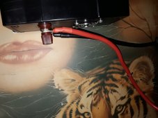
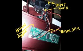
Well that flash cheap inverter already shit itself, where neg and pos screw on bottom they somehow incorrectly fitted and come real loose so I open top and fix,then I notice red and black wire from top board just hanging on by a strain of copper which I investigate further and notice main pin on power input bent over to make a plug off the top board fit because the stuck top on backwards and made things fit ,the last reading was 99v on inverter before it died,29v on Pv at the time only TV was on.Screenshot_20231214-213247_Gallery.jpg
Slip slop slapped together is what I got ,I didn't rebend the main pin but fixed everything better and the top on correct way so top board plug is in the clearing for it in the middle of the board, omg,anyway all been sweet until I turn on today and something inside sparked and flashed red and poped the fuse on battery so I shut off solar immediately then battery to work out what happened, left solar switch off and new battery fuse and see if it turn on,,na shes dead on arrival, so in the parts bin and back to old faithful which working well,,yes I did contact seller but no reply yet,wrong time of year ,20231214_212743.jpgScreenshot_20231211-153922_Trade Me.jpg
Nothing got warm or hot when this happened
Sorry guys and thanks
 
Well that was why I suggested not elcheaperating on the inverter. Sorry for your troubles.

FWIW QZRELB, MPPSolar, and Giandel have proven themselves as reliable lower-shelf products. I even hesitate to call them lower shelf, now. Mid-shelf maybe?
 
Aaahhh, paying that "Tuition Fee"! ;)
Ha yeh and probably not the last ? but sure careful now

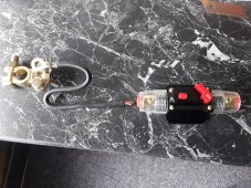
I do have question though please,,I have switch to turn off solar panel before the mppt controller 20231216_121442.jpg
I had a silly little 10amp fuse off the battery conected to the power inverter and the mppt controller together but I have this spare inline breaker, off on type, can I conect this like picture shows and have inverter and mppt into it .mayby not with this wire shown because I not know rating of it but just example. It's just good to turn system off when not needed or not here,,I used to take neg off battery but always sparks and dont get no spark if using kill switches
Thanks
 
Last edited:
Aaahhh, tube fuses, everyone's SECOND favorite fire starter!

A 10a fuse is only going to feed a 120w inverter, you'll have to step it up from there. On a budget the Chtaixi, T-Tocas, or Blue Sea DC breakers are decently regarded, but get those brands because the no-name knock offs are krap.
 
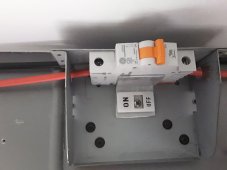
Ok yip on a budget , thanks for the links ,affordable to ,using one very similar to Chtaixi on my solar cable before the mppt controller to shut off input from panel20231216_163104.jpg.cant remember amps,cant read it when its stuck to the wall but I'll check.
Everything is working but I have system off till I get this battery kill switch..
As to my silly 10amp fuse that was just so if something happened like when cheap inverter gave up the fuse blew straight away without nothing heating up before fuse of trip switch pops.thats only reason,
I'm bit unsure still what to have amp off the battery, Do 100amp fuses trip immediately if a short occur? Only using TV, inverter shows it using 53watts how ever many that is,im still learning how things work .so many sites and info seems to vary so easy to get confused on what's what.even down to the AWG size wire and amps ,info varys for some reason
So regardless of amp fuse switch say 20,50,100,200 if there's a short will they trip out,,
Thanks again for help and info
 
Last edited:
Start with some basic math. Inverter wattage / voltage = amperage draw.
Amperage draw determines wire thickness.
Fuse/breaker size should be amperage * 1.2

So, in napkin math example:

1200w inverter / 12v battery = 100a max draw
100a of draw * 1.2 = 120a breaker/fuse
100a of draw calls for 4awg wire

Remember that fuses and breakers are designed to protect the wires. Most breakers are designed to allow surges for a little bit before they trip, so if you're drawing 102a across a 100a breaker it'll hold for a little bit in the hopes the load goes down, but drawing 200a across it will trip right quick.

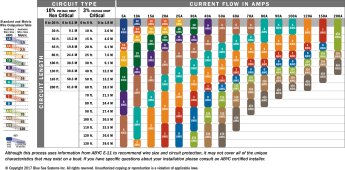
DC_wire_selection_chartlg.jpg
 
Ah good stuff,that I can make sense of,
I can count money but maths lol,think I missed those school days with regret
thanks for the chart too,makes things easier to understand,.Not all sellers here use AWG(American wire gauge) metric also as to why I was getting different specs on wire sizes looking at chart ,thought I was just stupid,oh little bit ,lot to learn
Thank you for patience and time and info,much appreciated
Ian
 
Since the OP is in NZ = 230volt AC system; his wiring after the inverter may be smaller than we (in N.America) are used to, due to his higher voltage. ie, a 1000W load on his AC system will be 1000/230 = 4.4 Amps
However on the DC side, his local household voltage doesn't change anything: 1000W load /12vDC = 83 amps. As already mentioned, upsizing for continuous duty/reduced line losses/heating is best practice.

The size of the battery to inverter cable should be large enough for the max the inverter MAY draw, not what it typically draws.
2000W inverter = 166 Amps @ 12volts, I would recommend 200A for wire sizing ie AWG 2/0 or 70mm metric. These wires should be as short as possible. (which also saves $$) There needs to be a suitable fuse on the DC side, T-Class would be recommended, ANL if the T-class is unavailable.
Fuses are sized to protect wires. For 2/0 (70mm) 200Amp fuse.
Glad to see the OP has been successful in getting his system up and running, and is now making it safer/better.
Thanks & thanks for confusing me some more lol,Wow taught me something,I had no idea voltage varys globally so had a look and interesting.
Looked at many cables all over the web now and under it most say same amps but some change,different specs for same wire so been bit confused by it all,
Still deciding on inverter type because some that been recommended have to come from Australia and not very cheap so have to have good look around , for now the old faithful 600w works well ,fan just annoys me when full sun 31v & 14.4 on inverter with TV going(42") .last week one still hot day this 600 inverter gave a HV alert and shut down ,age I guess mayby or can but cant really handle the juice from above. Its been on since and works fine I'm just in process of some safety side of things at the moment, waste of time buying anything till silly Santa goes south but few things to get.need 4 & 2awg by sound of it,that's cool,need battery to mppt controller cables because what's there is not battery cable( I got heaps of 8awg but 65amps I think) + fuses that I been told to get and lastly a inverter but that can wait for now.
Thanks and appreciate all info to feed the mind and keep the fire extinguisher in its holder ?
 
Another wire question please
20231218_184537.jpgScreenshot_20231218-190705_Gallery.jpg20231218_185035.jpg
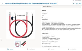
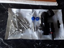
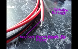
I'd like to move mppt but this requires a join, I planned to use the solar cable kit I first got with the black positive and the red negative color wire but I notice the size is different,the pre made port thing with the wires already fitted that I use has double insulation and other just single rubber,can I join these 2 sizes ,the tinned copper looks same size .the joins will be inside. I dont really see why this cant be done ,wire the same just ones double insulated ?‍♂️.
Main purpose is to bring all together so can buy shorter lengths of awg instead of wire goin everywhere

Only need to make 1 up since I can go direct into the inline trip switch before mppt controller with other
Thanks

Oh well must be ok if no reply .,sorry for dumb question,no more questions from me
 
Last edited:
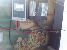
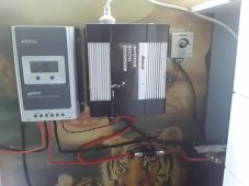
Well this what I was doin20231219_181533.jpg,20231219_202027.jpg,forgot me dimmer for lights.
Shorter cables ,my join was sweet,just trimmed insulation down to fit before crimping
Turned on for test and working well,it was working well before to lol,but much more semi organized, had wires all over the place ?.
Yip its basic but doin more than I expected it would for what I need ?
 
Last edited:
Hey here's something no one pic up onView attachment 180046View attachment 180047
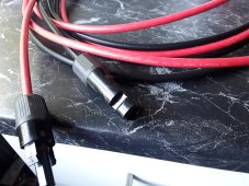
Ok my panel negative and positive on the panel and the solar wire extensions only plugged in reverse (dont know why yet) for the plugs to join.
On my solar controller I had to remember to put negative into positive and positive to negative.
It's not right (red in black) but works as it should but did I buy wrong sort or something---didnt even think to check when I brought
Is that my mistake or the seller put plugs on wrong cable? I write on picture to show neg and pos cable and yes panel cables have - & + on so cant get wrong but extensions are backwards and not cheap
What did I do no bigger but confused on that
This was wire I got
View attachment 180048
Hi. Those 5m cables you got from TradeMe - the cables in the advert are wired correctly - the positive on the panel is the male connector, so the positive on your cables from panel to controller will be the female connector. If you aren't sure, just connect it all up and put your multi-meter on the wires before going live. So it looks like the cables delivered were color-inverter?
 
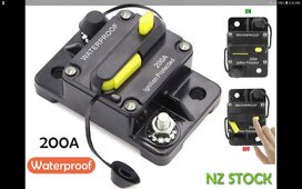
@NZ12VOLT ; that breaker on your solar cable looks like a C20 AC breaker. There are DC breakers available, and given its a caravan I'd recommend using a proper DC breaker as they have arc catchers, and will break correctly. AC breakers are not meant for this. On 12v DC for something like isolating a string of lights, an AC breaker is fine because you are using it for switching, not breaking. For your controller (Epever) you could be running anything up to 150v DC on that solar cable, so it pays to have a DC breaker.
 
Well this what I was doinView attachment 183862,View attachment 183884,forgot me dimmer for lights.
Shorter cables ,my join was sweet,just trimmed insulation down to fit before crimping
Turned on for test and working well,it was working well before to lol,but much more semi organized, had wires all over the place ?.
Yip its basic but doin more than I expected it would for what I need ?
Great to see you have swapped out the cable you had for the battery->inverter for a thicker cable. I think you have 16mm cable now, but if you find some 35mm cables that would give you even less voltage drop between battery and inverter with the kinds of currents you might be pulling.
 
Hi. Those 5m cables you got from TradeMe - the cables in the advert are wired correctly - the positive on the panel is the male connector, so the positive on your cables from panel to controller will be the female connector. If you aren't sure, just connect it all up and put your multi-meter on the wires before going live. So it looks like the cables delivered were color-inverter?
ah thanks yeh it just didn't look right having a red negative color wire,to me negative is black colour
@NZ12VOLT ; that breaker on your solar cable looks like a C20 AC breaker. There are DC breakers available, and given its a caravan I'd recommend using a proper DC breaker as they have arc catchers, and will break correctly. AC breakers are not meant for this. On 12v DC for something like isolating a string of lights, an AC breaker is fine because you are using it for switching, not breaking. For your controller (Epever) you could be running anything up to 150v DC on that solar cable, so it pays to have a DC breaker.
Thanks again ,good info,I do have this comingScreenshot_20231229-174612_Trade Me.jpgbut slow due to couriers, Not even sure if this correct breaker off on switch but still looking to improve my little project ,its been running last week with no issues, just my inverter is a baby but work well running TV, phone charger,cloudy days the system loves, full sun the poor inverter sits on 14.4 almost its HV cut off because the PV input to my battery I cant use the power its making so shut it down as to not cook my only inverter,this was another thought I had with the BT50 was to go into USER setting and lower the 16v over voltage cut off and couple other settings like in a clip I watch,, still looking at those inverters no more cheap ones lol.,
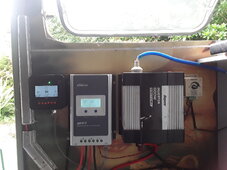
I did have a BT-50 ordered which arrived today so got that hooked up so I Can learn and get a idea of what's goin on ,read alot,watched few vids on YouTube to understand the parameter side of it,,the mppt works the same so mayby a helpful gimmick or unnecessary for small system
20231229_151501.jpg.And still waiting for some 4awg wire to arrive
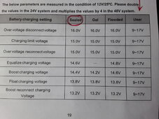
Totally agree on the tube type breaker ,rookie purchase lol,looked good but didn't investigate them at all,I just presumed it will do but def not,
Yip the inverter wires at moment are 5awg ,the 4awg not arrive yet so 5 it was ,I have been looking at battery isolation switches as well and probably will get one when all in open and deliverys are normal,,and I have a feeling this battery breaker is not the right thing ,I should have ask again but i will get another if no good
Awsome and thank you and safe merry xmas to all,,,,,and dont ask me why this post is all somehow paragraphed like it is,,it just does it
 
Last edited:
Ok my curiousity is asking about the charging limit voltage and this thought is to see if I drop the charging limit will that reduce the voltage going to the inverter.? I think its bit much for it to sit high at 14+volts on sunny days with 31volts from the PV since my appliances dont use much power ,hey power is cool dont get me wrong but this inverter holds a nice 12.9 to 13volts with 42" TV going without out the fan even starting but over that and fans a pain to listen to,sometimes constant but mostly revving Highly very intermittently which tells me it's starting to work hard cause of the high PV input and I can't use enough power to drop the voltage at the inverter,,sure the MPPT stops it overcharging, but on bright days, that's why cloudy days seem just right,,confused yet lol,,picture is default MT50 settings for sealed battery at 15volt....USER can go between 9 and 17volts,,me want to try 14volts for charging limit voltage setting ,might have to adjust couple more but MPPT almost identical presets
Will this carm things down for the inverter, the videos I watch seem safe but they clever buggers,I know I need a better one ,been looking,not cheap ,
20231229_193615.jpg
Still lot to learn dispite the amount of reading and do have slight hesitation of adjusting parameters till i know if it's safe to do so,manual never explains things properly and YouTube it's like monkey see monkey do type situation ha
Be interesting to see what the panel is producing on the BT50 display, is slightly more informative to see than going through modes with just the mppt controller which keeps changing by itself
Thanks
 
Last edited:
You'll be OK to drop your voltage limit to make your inverter happy. As for the extra power, your equipment is having a conversation along the lines of:

SCC - "Hey guys, I got power to spare, who wants some?"

Battery - "I could use some, pass me them amps."

Inverter - "I gotta feed this guys TV, send me some of those watts too!"

Panels - "I think I can, I THINK I can."

Battery - "Ok, I'm full, no more for me."

Inverter - "He fired up the microwave! HELP!!"

Battery - "Here's some amps dude, I'll get them back from the panels tomorrow."

And so on, and so on. Your panels will only produce power when the loads ASK the controller for power. If the battery is full and the sun is shining, the panels will feed the liads. If the battery is empty it gets dibs and the controller tries to max out as much charge as it can get from the sun.
 
Back
Top