Hello Bundyblu,
I'm starting a new project to extend to JK-BMS a 6 months logger I made for DALY BMS .
I already found all the protocol info I need to communicate with JK , the only doubt I still have is coming from the DS :
http://www.jk-bms.com/en/Upload/2023-12-05/1746328565.pdf
I will use UART connector to be compatible with my current HW.
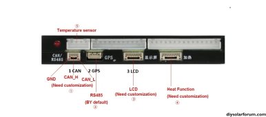
UART connector is "P5" on JK meant for GPS.
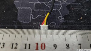
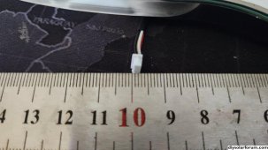
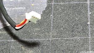
Is a 4 pin JST 1.25 ( or it should be )
Pin P5.1 is stated to be VGPS ( ... close to B+ ) .
QUESTION: Have you tested this Pin during your development ? is really B+ ( on 16S it should be around 50V that makes no sense for me )
Thanks for replying.
P.S. asking because I don't have a JK-BMS - I will work blindly this time .... simply trying to add the JK protocol .
For your ( and my fun ) this is a Zoom IN of a 24h log from my logger
")
notes - yellow boxes and red arrow are added later
View attachment 185810