diy solar

diy solar

Basic LiTime 100Ah + two flexible 140W panels issues

kodak

New Member
Joined
Apr 2, 2022
Messages
14
Hi, I have recently bought
basic LiTime 100Ah battery
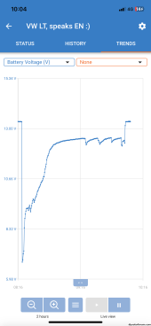
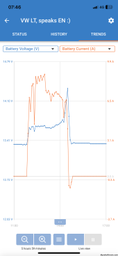
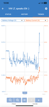
After couple of days of uninterrupted usage yesterday I got cut off from the cells by BMS just by plugging 5W usb charger (through smart solar).
What could be the reason? The day before I have fully charged it (next pic).
LiTime support is not very helpful.
I have just two ideas: I did a short in cigarette lighter socket (but I see no burn marks there) or BMS has some bad solder points. What was new is that the night was coldest so far for the battery: I recorded 7C just below it as a minimum but this battery has no temp sensing AFAIK.
Any ideas/recommendations?
 

Attachments

  • IMG_0146.png
    IMG_0146.png
    77.9 KB · Views: 14
  • IMG_0143.png
    IMG_0143.png
    103.7 KB · Views: 14
Looks like you engaged short circuit protection.

Also looks like your battery might be imbalanced at the top due to the abrupt cut of current to 0A, but it's hard to tell on that time scale. If it happened gradually over the course of at least a few minutes, it's probably fine.
 
Looks like you engaged short circuit protection.

How fast does it act? Why no burn marks?

Also looks like your battery might be imbalanced at the top due to the abrupt cut of current to 0A, but it's hard to tell on that time scale. If it happened gradually over the course of at least a few minutes, it's probably fine.
Yes I was also curious why charging last only couple of minutes after reaching 14.4V. I have tail current set to 2A and absorption fixed of 24h. Could I somehow prolong charging?
 
How fast does it act? Why no burn marks?

Damn fast. You'll get a spark, but burns are hit and miss.

Yes I was also curious why charging last only couple of minutes after reaching 14.4V. I have tail current set to 2A and absorption fixed of 24h. Could I somehow prolong charging?

First... 24 hour absorption? That's insane. 30 minutes max @ 14.4V unless charging at high current.

Since you're likely not charging at 50A, the voltage climb at the end happens very late and fast where the battery may already be essentially full when it hits 14.4V, and a tail current of 2A on LFP may be terminating it very quickly.

The only way to extend charging is to disable tail current.

You should watch the charge termination live where the updates happen about every two seconds. That will give you a better idea if the MPPT is terminating charge, or if the BMS is cutting it off. Another indicator of a BMS charge cut-off is the MPPT voltage may spike well above absorption. The battery is removed from the charge circuit, and the MPPT can't clamp down fast enough to prevent a voltage spike.

Given the info you provided, I suspect your charges are terminating normally based on tail current.
 
Damn fast. You'll get a spark, but burns are hit and miss.

Ok then I am assuming a short (waiting for better connectors currently)

First... 24 hour absorption? That's insane. 30 minutes max @ 14.4V unless charging at high current.

I knew that going below 2A will terminate it so I have set time to the max available.

Since you're likely not charging at 50A, the voltage climb at the end happens very late and fast where the battery may already be essentially full when it hits 14.4V, and a tail current of 2A on LFP may be terminating it very quickly.

The only way to extend charging is to disable tail current.

You should watch the charge termination live where the updates happen about every two seconds. That will give you a better idea if the MPPT is terminating charge, or if the BMS is cutting it off. Another indicator of a BMS charge cut-off is the MPPT voltage may spike well above absorption. The battery is removed from the charge circuit, and the MPPT can't clamp down fast enough to prevent a voltage spike.

Given the info you provided, I suspect your charges are terminating normally based on tail current.
Charge drop took couple of minutes.

I am charging below 10A. I have another issue of getting 150W max from nominal 2x140W panels. I did MPPT heat sink. Now I wait for new MC4 connectors and them I am out of ideas.
 
I knew that going below 2A will terminate it so I have set time to the max available.

It terminates based on the first satisfied.

Recommend you change to 30 minutes fixed and disable tail current.

Charge drop took couple of minutes.

Probably normal termination.

I am charging below 10A. I have another issue of getting 150W max from nominal 2x140W panels. I did MPPT heat sink. Now I wait for new MC4 connectors and them I am out of ideas.

Location?
Orientation of panels?
Vmp of panels?
Imp of panels?
MPPT output current rating?
 
It terminates based on the first satisfied.

Recommend you change to 30 minutes fixed and disable tail current.
Ok. I will give it a try.
Probably normal termination.


Location?
Tessaloniki, Greece
Orientation of panels?
Mobile so always aimed at the Sun.
Vmp of panels?
18.7V
Imp of panels?
7.5A
In series so 40V/7.5A max
MPPT output current rating?
75/15 so within the limits (limited by thermals only)
 
Ok. I will give it a try.

Tessaloniki, Greece

You're at 40°N latitude, so you're NEVER going to get max power out of your panels while the sun is in the Southern hemisphere.

Mobile so always aimed at the Sun.

@ 60° tilt?

I checked irradiance values for this time of year at your location for a panel tilted at 40° (your latitude), and it's typically 700-800W/m^2. Panel ratings are based on 1000W/m^2.

Heating of the cells above 25°C also lowers the Vmp and power output of the panel.

If your panels have a NOCT or NMOT rating, that's a much better indicator of actual performance.

also worth putting a clamp DC ammeter around each panels' wires to confirm you're actually getting current out of both.

75/15 so within the limits (limited by thermals only)

MPPT 75/15 - the 15 is OUTPUT current. It also happens to be limited to 15A input current.

The maximum you'll ever get out of that controller is 220W @12V system voltage. 280W is over-paneled.
 
Thank you again for your input. I still have issues with this battery. It is a second time that charging quickly goes into float state after couple hours of moderate use (windows laptop 10-50W, 80Wh consumed since last top up as per VictronConnect) so it must be drained some. What could be the reason? I start to be fed up with this battery :(
Edit: I have just saw your signature - bad connections...
Edit: as per being over-panelled: as mppt controls charging current I feel safe being below 75V and below 15A and yes - I am aware of 220W limit
Edit: indeed bad connection- it charges fine after reseating battery cables; I hate those 6mm2 screw connectors on blue boxes; thank you for your signature
 

Attachments

  • IMG_0223.PNG
    IMG_0223.PNG
    125 KB · Views: 2
Last edited:
Thank you again for your input. I still have issues with this battery. It is a second time that charging quickly goes into float state after couple hours of moderate use (windows laptop 10-50W, 80Wh consumed since last top up as per VictronConnect) so it must be drained some. What could be the reason? I start to be fed up with this battery :(
Edit: I have just saw your signature - bad connections...
Edit: as per being over-panelled: as mppt controls charging current I feel safe being below 75V and below 15A and yes - I am aware of 220W limit
Edit: indeed bad connection- it charges fine after reseating battery cables; I hate those 6mm2 screw connectors on blue boxes; thank you for your signature

I still struggle to consider bad connections in my first response! Glad you read it!
 
Ok, there was a cold solder on battery positive terminal of smart solar mppt wire connector; thank you victron's manufacturing plant; I hope it ends my journey with this mppt brick/solar setup
 
Last edited:
Any advise on opening litime battery box? I need to add heating and temperature sensor.
Edit: it is now opened
 
Last edited:
You're at 40°N latitude, so you're NEVER going to get max power out of your panels while the sun is in the Southern hemisphere.


@ 60° tilt?

I checked irradiance values for this time of year at your location for a panel tilted at 40° (your latitude), and it's typically 700-800W/m^2. Panel ratings are based on 1000W/m^2.
Can you please recalculate it for today? Now when I have corrected bad solder point I do not get voltage drops while moving the cables which is good but I am still at 130W from both panels at once in a clear sky (~50%)
 
Can you please recalculate it for today? Now when I have corrected bad solder point I do not get voltage drops while moving the cables which is good but I am still at 130W from both panels at once in a clear sky (~50%)

Looking at past data for this time of year, peak yield will be about 75% rated at noon, with the panel facing due south, clear skies and at 40° tilt.

Not sure if we've discussed it, but there also has to be a place for the power to go. If the battery is full or in absorption mode, it will only take in what it needs.

The best way to ensure you're drawing max from the panels is to power a load that's larger than your array power.
I have 100Ah LiFePO4 which soaks energy like a sponge so no problem with the reception
It seems I still have a bottleneck somewhere :(
 
Ok, I think I have an imperfect set of (flexible) panels
Could you please help me understand its configuration?
I assume there are 2 serially wired sets of 12 parallel 9V strings (giving 18V panel)
IMG_0332.jpeg
I have correct open circuit voltage but lower than expected current flow
I have found places which are potentially non-contact points with an example below
IMG_0333.jpeg
Questions:
- will such non-contact point result in correct panel voltage but lower current? I assume yes
- are those points (string-busbar junction) soldered or just holding based on lamination?
I am thinking about removing the laminate behind such spot to realign traces correctly and covering it back with a silicon

Edit: those points are spot-welded; pads below cells are quite big so even in such misalignment from the image - there is still contact made; I assume there are still no-contact points there but they are not based on misalignment; any ideas how to find dead strings?
 
Last edited:
Back
Top