You are using an out of date browser. It may not display this or other websites correctly.
You should upgrade or use an alternative browser.
You should upgrade or use an alternative browser.
Batteries are being overcharged by All-in-one Inverter
- Thread starter KolinCancer
- Start date
KolinCancer
New Member
First I went fast assuming the video could b paused. Now i know otherwise. Kinda weird. My bms is disabled right now. I believe it was on sla. I had a lot of issues getting the bms to even b recognized on my inverter. Ultimately i had to set my batteries in pylon and used CAN and UZE. The only part of the bms that made any sense here was i had to use the Can/485 port. I tried using the pylon setting on both 485 and can and i would get a error.Are you using closed loop (BMS to Inverter communications)?
Looking at your video (you don't pause long enough on some settings) it appears you selected "CAN" for the "RS485 Communications" (menu item #32) and "UZE" (menu item #33) for the "BMS Communications".
Just looking at the information your provided in the various product manuals (excellent, always helps) it does appear (although I don't know for sure) that your batteries are very much like SOK and SunGoldPower rack mounted batteries.
The SOK and SGP batteries use the "Pylontech" protocol when communicating with the inverter.
I assume you have the Inverter connected to the "RS485-ICAN port (left jack, not the right of the jack pair) and all the batteries are daisy chained on the RS485-2 ports (either jack to either jack).
If the above is true, try selecting "485" for menu item #32 and "PYL" for menu item #33.
When you select "L16" for menu item #8 the firmware simply applies default settings for battery charging.
If BMS communications exist the BMS will override #9 and #11 (and some others). If BMS communications fails (i.e. the cable is disconnected) the firmware will revert to the default #9 and #11
I am not familiar with your batteries so I do not know for certain what I have just described will work for you. It won't hurt to give it a try. By selecting "485" and "PYL" the worst that can happen is you get a BMS Communications fault, just go back to your original settings.
KolinCancer
New Member
Update - Ah crap didn't see it had already progressed that far and can't find where to delete a post.
Tagging @42OhmsPA for input as the PowMR 10K is just a rebrand of his SRNE.
Also do you know if each pv jnput can handle the 500v 22amps? I have 10 400w q cells in series about to add 10 more in parallel to that (would b more happy about that if it would stop over charging via solar but its kinda needed) the v and a at mpp would b 371.3v and 21.54. That setup would just get me incredibly close to the amps max (in a open circuit setting) on one of the pv inputs im just wondering if adding more was possible on the other pv inputHmm. There goes my idea lol.
Let's you monitor your system in near real time, charts data, allows you to change basic parameters.
Somewhere around 53.5V.
This is when charging will kick back in after they have already reached full.
All my settings are here. They've been tweaked a bit since but will still work fine.
Post in thread '2 Mwh SRNE ASF48100U200-H 10kw.' https://diysolarforum.com/threads/2-mwh-srne-asf48100u200-h-10kw.67809/post-905676
42OhmsPA
What's in a title?
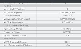
Yes. Each one is 22A and 500V.Also do you know if each pv jnput can handle the 500v 22amps? I have 10 400w q cells in series about to add 10 more in parallel to that (would b more happy about that if it would stop over charging via solar but its kinda needed) the v and a at mpp would b 371.3v and 21.54. That setup would just get me incredibly close to the amps max (in a open circuit setting) on one of the pv inputs im just wondering if adding more was possible on the other pv input
What's the VOC of your panels?
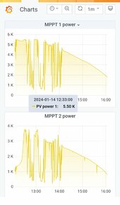
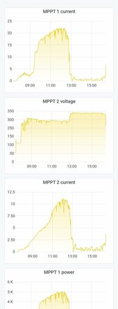
marionw
Solar Enthusiast
Can you provide a picture of your battery stack that clearly shows the cabling between the batteries and the dip switch settings.
In addition what are the battery addresses? Normally the inverter wants to talk to the battery with address 1.
For most batteries address 1 places that battery into host/master mode which in turn supports a very specific inverter to battery communication sequence and the inverter needs to be connected to this battery.
For Open Loop setup:
Disconnect the Battery BMS cable to ensure there is no BMS Communications.
Set RS485 Communications Menu Item # 32 to SLA
Set Battery Type Menu #8 to L16 then:
Record the L16 settings for:
【15】<【12】<【04】<【14】<【35】<【37】<【05】<【09】=【11】
Set Battery Type (Menu Item #8) to User and then set in particular menu items #9 and #11 to something closer to 54.5 to 55.2
Menu item #7 Battery Charging Current and Menu item #28 Max Utility Charging Current also affect battery charging with #7 being driven by BMS communications and this may be why generator charging if different than PV Array charging.
As always you can operate in open loop (no BMS communications), set your battery type to user and then adjust the battery charging parameters to prevent overcharging.
In the end it would be nice to have the inverter correctly talking to the batteries so you can decide to use open or closed loop. Just need to figure out why the BMS to Inverter communications are not working.
Have you downloaded the "MJBDTools V2.B-20230720.exe" from the cloudnewenergy.com website and are you able to view each battery with the software. This will tell you what the BMS is using for Cell Over Voltage Alarm (OV) and Cell Over Voltage Protection (OVP) as well as Pack Over Voltage Protection (PACK OVP).
The charts you posted, are they from Solar Assistant, and if so how is it communicating with the batteries and the inverter.
Lighthouse Beacon
Following the Light
My gen1 (round) screen srne10k overcharged like this sometimes also, didn’t matter if comms were enabled or what inverter settings were, my batts would eventually disconnect. This would happen more often when I had alot of PV coming in and not much load. I added more circuits to my solar panel ( I put every ceiling fan in house on the solar circuit and left them on all day) I also added several other inductive (coil magnet) loads like my wife’s backyard garden waterfall pump, it use to be on a timer, I just let it run all day. After I put more loads on the inverter it got better about throttling down all the pv power coming in. It’s almost like it couldn’t find anywhere to dump the power so it was over dumping into the batts. That gen1 eventually had a board failure tho, this gen2 doesn’t do that. I hated that round screen srne10k.Tried what u said. Still over charging without bms. Ive told it to not charge it to 59.9v (56.4v is what i told it to do to b exact) and it still does it. So maybe now u could offer some advice rather then read the manual or contact the manufacture because powmr is garbage. Ill include a video as well
Put more load on the inverter and see if it keeps “leaking” so aggressively to batts
That’s the only way I could stop mine was by loading it up more during peak hours
Do you hear the machine “whine” sometimes? Like capacitors singing abit, a very high frequency? Almost like you can’t hear it? Mine started doing that before the power board went
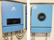
Last edited:
KolinCancer
New Member
440vYes. Each one is 22A and 500V.
What's the VOC of your panels?
View attachment 194202
View attachment 194203
KolinCancer
New Member
Ill take a picture later on as im not home right now. I do have that software and it communicated fine. I dont believe its a bms or settings problem since even without the bms it would still overcharge even if i set the absorb and bulk at 55 it would still go past to 59.9Can you provide a picture of your battery stack that clearly shows the cabling between the batteries and the dip switch settings.
In addition what are the battery addresses? Normally the inverter wants to talk to the battery with address 1.
For most batteries address 1 places that battery into host/master mode which in turn supports a very specific inverter to battery communication sequence and the inverter needs to be connected to this battery.
For Open Loop setup:
Disconnect the Battery BMS cable to ensure there is no BMS Communications.
Set RS485 Communications Menu Item # 32 to SLA
Set Battery Type Menu #8 to L16 then:
Record the L16 settings for:
【15】<【12】<【04】<【14】<【35】<【37】<【05】<【09】=【11】
Set Battery Type (Menu Item #8) to User and then set in particular menu items #9 and #11 to something closer to 54.5 to 55.2
Menu item #7 Battery Charging Current and Menu item #28 Max Utility Charging Current also affect battery charging with #7 being driven by BMS communications and this may be why generator charging if different than PV Array charging.
As always you can operate in open loop (no BMS communications), set your battery type to user and then adjust the battery charging parameters to prevent overcharging.
In the end it would be nice to have the inverter correctly talking to the batteries so you can decide to use open or closed loop. Just need to figure out why the BMS to Inverter communications are not working.
Have you downloaded the "MJBDTools V2.B-20230720.exe" from the cloudnewenergy.com website and are you able to view each battery with the software. This will tell you what the BMS is using for Cell Over Voltage Alarm (OV) and Cell Over Voltage Protection (OVP) as well as Pack Over Voltage Protection (PACK OVP).
The charts you posted, are they from Solar Assistant, and if so how is it communicating with the batteries and the inverter.
42OhmsPA
What's in a title?
KolinCancer
New Member
Have u had to put the extra loads on the new inverter? To me it just seems like a bad onboard mppt which just has no idea what to do with the excess power.My gen1 (round) screen srne10k overcharged like this sometimes also, didn’t matter if comms were enabled or what inverter settings were, my batts would eventually disconnect. This would happen more often when I had alot of PV coming in and not much load. I added more circuits to my solar panel ( I put every ceiling fan in house on the solar circuit and left them on all day) I also added several other inductive (coil magnet) loads like my wife’s backyard garden waterfall pump, it use to be on a timer, I just let it run all day. After I put more loads on the inverter it got better about throttling down all the pv power coming in. It’s almost like it couldn’t find anywhere to dump the power so it was over dumping into the batts. That gen1 eventually had a board failure tho, this gen2 doesn’t do that. I hated that round screen srne10k.
Put more load on the inverter and see if it keeps “leaking” so aggressively to batts
That’s the only way I could stop mine was by loading it up more during peak hours
Do you hear the machine “whine” sometimes? Like capacitors singing abit, a very high frequency? Almost like you can’t hear it? Mine started doing that before the power board went
View attachment 194243
KolinCancer
New Member
Need clarification So each pv input can handle up to 500v and up to 22amps but only 5500w? Maybe thats y ive been having issues? I cant imagine so since other users have had the same over charging issues but itd b nice if it was the issue. Ive been considering changing it to a 5 series 2 parallel. My hold out there would b conduit fill and it would become alot harder to upgrade the solar system. But if what im interpreting is correct i wouldnt b able to run 10s2p w my panels anyway cuz they would b well over the wattageDid you figure out cold weather calculations to make sure you don't go over 500V?
Note you are already over the working voltage range of the MPPT.
View attachment 194343
Kenny_
Solar Addict
What I've seen/read/experienced is that you can't exceed either the voltage or the current unless you want serious damage. (I destroyed an Ecoflow River 2 that way).Need clarification So each pv input can handle up to 500v and up to 22amps but only 5500w? Maybe thats y ive been having issues? I cant imagine so since other users have had the same over charging issues but itd b nice if it was the issue. Ive been considering changing it to a 5 series 2 parallel. My hold out there would b conduit fill and it would become alot harder to upgrade the solar system. But if what im interpreting is correct i wouldnt b able to run 10s2p w my panels anyway cuz they would b well over the wattage
KolinCancer
New Member
Correct but 22amp and 500v is 11000 watts. But according to the documention that was shared each input can only handle 5500wWhat I've seen/read/experienced is that you can't exceed either the voltage or the current unless you want serious damage. (I destroyed an Ecoflow River 2 that way).
Kenny_
Solar Addict
VOC is different than the mppt voltage input etc... but yes 425 at 22a is still 9350W but but but they still have to be considered separately...you can't exceed either the spec'd voltage or current
42OhmsPA
What's in a title?
Correct.Need clarification So each pv input can handle up to 500v and up to 22amps but only 5500w?
Possibly.Maybe thats y ive been having issues?
You can be over the wattage but the MPPT will not make use of it.I cant imagine so since other users have had the same over charging issues but itd b nice if it was the issue. Ive been considering changing it to a 5 series 2 parallel. My hold out there would b conduit fill and it would become alot harder to upgrade the solar system. But if what im interpreting is correct i wouldnt b able to run 10s2p w my panels anyway cuz they would b well over the wattage
I have ~25A on each MPPT, it will only utilize 22A.
Do not go over the voltage!
I would not run that high of VOC.
Lighthouse Beacon
Following the Light
@42OhmsPA is right, if you're that close to max voltage that's going to be the issue. I have 24 panels on my setup but only use 20 for that same reason. I don't even go over 400V now. I was warned several times by forum members to not exceed that voltage especially when you do the cold weather calculations.Need clarification So each pv input can handle up to 500v and up to 22amps but only 5500w? Maybe thats y ive been having issues? I cant imagine so since other users have had the same over charging issues but itd b nice if it was the issue. Ive been considering changing it to a 5 series 2 parallel. My hold out there would b conduit fill and it would become alot harder to upgrade the solar system. But if what im interpreting is correct i wouldnt b able to run 10s2p w my panels anyway cuz they would b well over the wattage
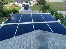
KolinCancer
New Member
New video by Leon Kolin
 photos.app.goo.gl
KolinCancer
New Member
Sounds good. Ill alter that connection today from 10s1(or 0)p to 5s2pCorrect.
Possibly.
You can be over the wattage but the MPPT will not make use of it.
I have ~25A on each MPPT, it will only utilize 22A.
Do not go over the voltage!
I would not run that high of VOC.
KolinCancer
New Member
If i go over amps will it just limit it? If i do it would b by about .4amps but im just wonderingSounds good. Ill alter that connection today from 10s1(or 0)p to 5s2p
42OhmsPA
What's in a title?
Yes.If i go over amps will it just limit it? If i do it would b by about .4amps but im just wondering
Similar threads
- Replies
- 20
- Views
- 2K


