


KolinCancer
New Member
I have an offgrid setup that has been running well enough but id like it to be fully automated. Ill include links to all of the components in my setup but basically im trying to figure out how to use my inverters dry contacts to auto start my generator. my current setup is generator to ats. breaker on my panel to a 240v timer to the utility side of my ats. the ats load runs to my ac in of my inverter and then ac out runs to panel. i just added a battery so i have about 18hrs of autonomy so the timer has been kinda useless seeing as how my solar (10x400w qcell panels in series) is enough to keep the system alive and recharge the batteries. The BMS on my inverter and batteries are functioning well. However with rainy season coming up it would b nice to completely automate the system so if we get no sun for multiple days the generator will just keep the system alive. I appreciate any information just keep in mind while ive been going to school for electric this is a bit outside my scope and would appreciate full explanations.
Generator & ATS Switch:
 Manual:
Inverter:
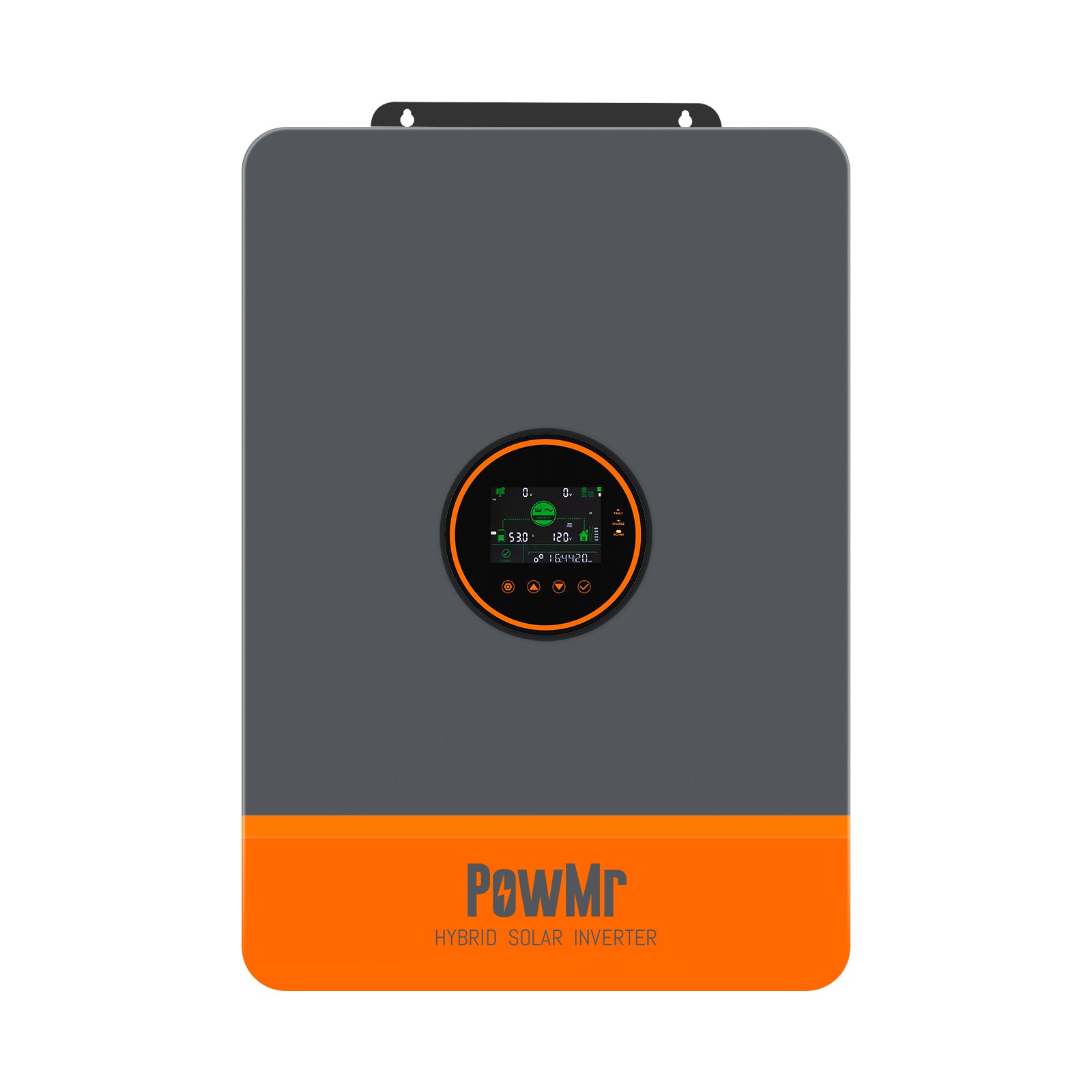
 powmr.com
Inverter Manual:
powmr.com
Inverter Manual:
User Manual of POW-SUNSMART 10K
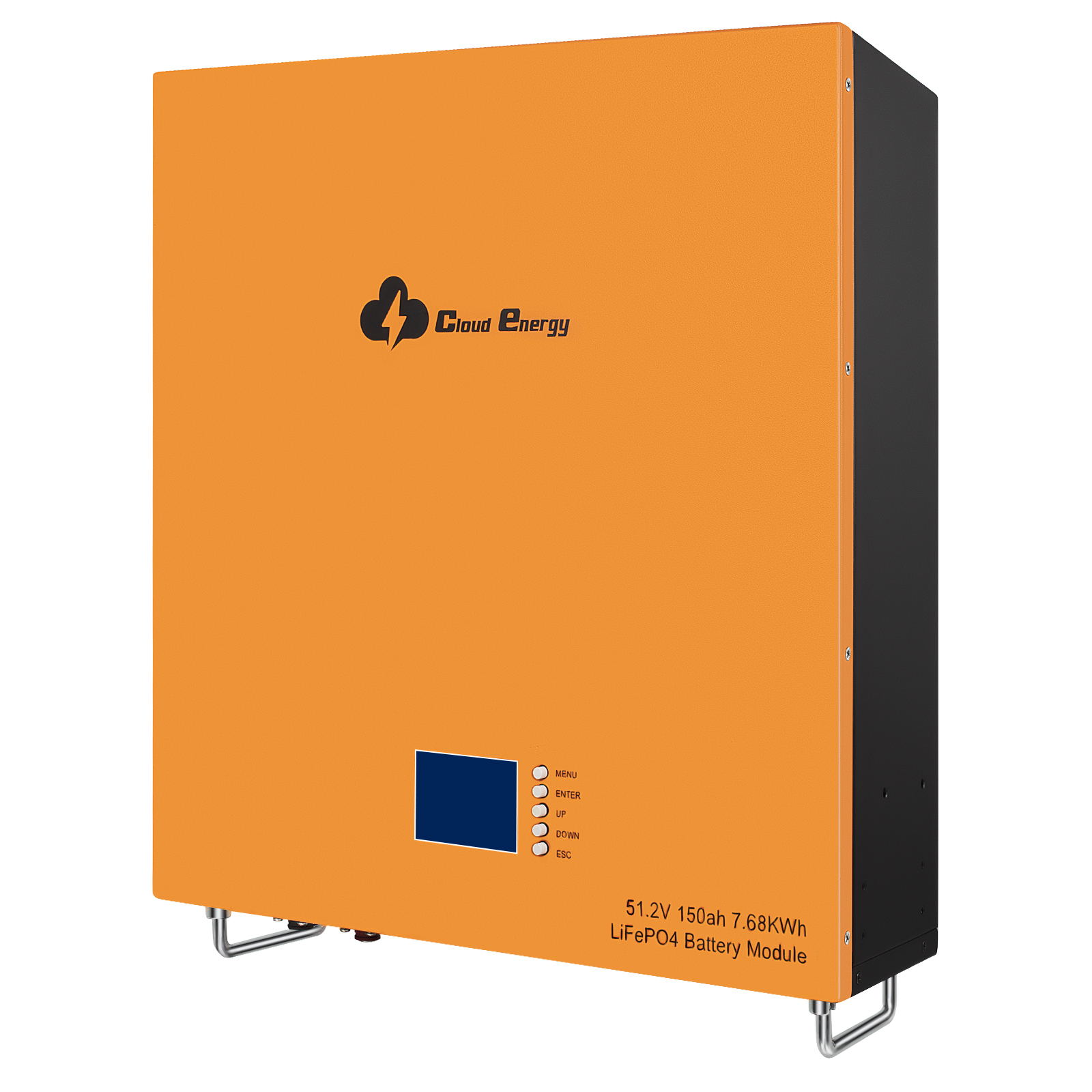
Batteries:
 cloudnewenergy.com
Solar:

 us.qcells.com
Datasheet:
us.qcells.com
Datasheet:
Generator & ATS Switch:
Inverter:
10KW 48Vdc Hybird Inverter 110/240Vac Split Phase
10KW 110Vac and 240Vac Split Phase Hybrid Inverter Charger for 48V batteries ensures a stable and balanced power supply.
User Manual of POW-SUNSMART 10K
Batteries:
CL48-150B
Nominal Voltage/Nominal Capacity: 51.2V/150Ah wall-mounted with 7.68Kwh energy
cloudnewenergy.com
Solar:
Q.PEAK DUO BLK ML-G10+ - Qcells North America
Introducing Q.PEAK DUO BLK ML-G10+: Setting the standard for solar excellence. Unleash maximum power and reliability with advanced technology.
us.qcells.com