diy solar

diy solar

Auto Starting My Generac

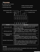
thats what i have read however in my manual it says pin 1&3 output 5v and that works. and it also says pins 5/6/7 outputs 125vas/1a 230vac/1a, 30vdc/1a. am i just misinterpreting that

Some of the inverters (like mine for example) have certain pins available to power some small DC devices like say a Raspberry Pi or something off of the inverter, so could use a 5v it provides for something like that.
 
So focusing on the 'Generator remote start/stop' function of the 'Dry Contact' connector, they speak of the relay being NO/NC (normally open vs normally closed) terminals, so that means it has 3 secondary-side switching relay terminals on it (Pin 5 is Common, Pin 5 to 6 may be NO, and pin 5 to 7 may be NC)... Normally, typically means when relay primary coil is off (relaxed).

One terminal goes to the pivot (Common) of the switch. Another terminal for the NC means it is closed to the pivot terminal (Common) when the relay is not engaged, and the 3rd terminal NO, will become closed to the pivot (Common) terminal when relay is engaged (when this engages, it opens the NC terminal. The pivot (Common) just pivots back and forth between the NC and NO terminals when the relay primary coil is engaged or relaxed.

EDIT:
So it sounds like when the battery gets low, Pins 5 to 6 are opened (5 and 7 are closed), and when battery is full Pins 5 to 6 are closed (5 to 7 are open).

The last part (which has poor translation) where they show: 125Vac/1A, 230Vac/1A, 30Vdc/1A, is just letting you know the current limits you are allowed to run across Pins 5,6,7 (at the 3 listed voltage ratings), so you don't burn up the contacts. It basically means don't run a load more than 1A across those terminals.
 
Last edited:
So focusing on the 'Generator remote start/stop' function of the 'Dry Contact' connector, they speak of the relay being NO/NC (normally open vs normally closed) terminals, so that means it has 3 secondary-side switching relay terminals on it (Pin 5 is Common, Pin 5 to 6 may be NO, and pin 5 to 7 may be NC)... Normally, typically means when relay primary coil is off (relaxed).

One terminal goes to the pivot (Common) of the switch. Another terminal for the NC means it is closed to the pivot terminal (Common) when the relay is not engaged, and the 3rd terminal NO, will become closed to the pivot (Common) terminal when relay is engaged (when this engages, it opens the NC terminal. The pivot (Common) just pivots back and forth between the NC and NO terminals when the relay primary coil is engaged or relaxed.

EDIT:
So it sounds like when the battery gets low, Pins 5 to 6 are opened (5 and 7 are closed), and when battery is full Pins 5 to 6 are closed (5 to 7 are open).

The last part (which has poor translation) where they show: 125Vac/1A, 230Vac/1A, 30Vdc/1A, is just letting you know the current limits you are allowed to run across Pins 5,6,7 (at the 3 listed voltage ratings), so you don't burn up the contacts. It basically means don't run a load more than 1A across those terminals.
Yeah, the wording for pins 5,6 and 7 is ambiguous. Just remove the word normal.
 
Would you be able to draw a picture or make a diagram showing the above description so we could wrap head around the proposed ATS wiring?
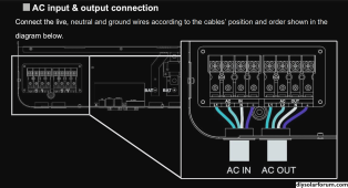
Im sorry you asked for a drawing from me but here it is. the panel is on the next page of the file. also the image w ac in and out would b my inverter
 

Attachments

  • New Microsoft Word Document.docx.pdf
    226 KB · Views: 10
Last edited:
thank you

Sure np.. I guess I don't understand whether or not you have AC grid power or off-grid / generator only, can you clarify? And where it ties in.. If you are off-grid and only have generator as an aux AC source, then you don't need an ATS...
 
Sure np.. I guess I don't understand whether or not you have AC grid power or off-grid / generator only, can you clarify? And where it ties in.. If you are off-grid and only have generator as an aux AC source, then you don't
Yes im off grid. So after installing the 2 wire start stop i should remove ats run the gen to ac in and have the ac out run to the panel?
 
Yes im off grid. So after installing the 2 wire start stop i should remove ats run the gen to ac in and have the ac out run to the panel?

Yeah, the inverter already does ATS function, just study all the settings so you can set everything to the behaviors you want...

When the generator is charging batteries, the inverter will go into bypass mode so it will supply AC loads to your panel while charging batteries.
 
Yeah, the inverter already does ATS function, just study all the settings so you can set everything to the behaviors you want...

When the generator is charging batteries, the inverter will go into bypass mode so it will supply AC loads to your panel while charging batteries.
sounds good thank you. ive order the 2 wire start stop and ill post my results. thanks for the quick replies
 
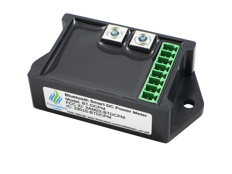
If you want to consider a slightly different solution with a little more customization potential, the Thornwave Labs Powermon is a good unit.

 
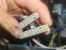
So my 2 wire start just got here however ive ran into an issue. I have a 2016 or later version and it says to insert into j1-18 and j2-10 but both of those are full. On my 20 pin only 5, 8 and 13 are open and on my 16 pin only 2, 13 and 15 are open. Whats going on here (im dumb and looking at it backwards)
 
Last edited:
oddly enough it appears that the ones directly above and below (respective to image and pin option) is open (I was looking at it backwards)
 
Last edited:
One final question tho. Once i remove my ats how can i recharge my battery? I know the t1 would b the hot 120 but which would b the return
 
One final question tho. Once i remove my ats how can i recharge my battery? I know the t1 would b the hot 120 but which would b the return

Don't forget that the inverter has a battery charger and a built-in ATS. When you power the AC input on your inverter via the generator, once it sees the valid AC power source, the inverter will switch to bypass mode, powering all the loads in your house, and charging batteries at same time. When generator shuts back off, the inverter switches back on.


According to this diagram (from your manual link on first post), that is a 240v connection (L1 and L2) on your inverter:

1697547987575.png
 
Last edited:
On the Nexus controller neutral for the battery charger is designated 00.
 
Don't forget that the inverter has a battery charger and a built-in ATS. When you power the AC input on your inverter via the generator, once it sees the valid AC power source, the inverter will switch to bypass mode, powering all the loads in your house, and charging batteries at same time. When generator shuts back off, the inverter switches back on.


According to this diagram (from your manual link on first post), that is a 240v connection (L1 and L2) on your inverter:

View attachment 172669
I meant my generators battery not my power bank. Sorry for any confusion
 
Back
Top