MartyByrde
Off-Grid Innovator
For the smoke damage to the board I would clean it off with some 99% isopropal alcohol and an acid brush or tooth brush, just in case it is slightly conductive.
I have 90% will that work?


For the smoke damage to the board I would clean it off with some 99% isopropal alcohol and an acid brush or tooth brush, just in case it is slightly conductive.
I wanted to add some room for margin. I spoke with Daisy about using a crimped 2/0 wire instead of the pop on connectors that came with the kit. I also don’t have enough female connectors now. She spoke with Docan’s engineer and said it would be okay to remove one of the male connectors then bring the 2/0 wire through the hole to connect to the bus. Would it be better to connect this in between DK-1 or go directly to the bus with the fuse? Thoughts on this approach?The good news is IF the BMS still works, after reconnecting things directly, without washers in between, you have a spare set of terminals, so, with new cables you should be able to get these up and running.


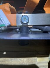
Yes that was just to show the damage and see if it was recoverableAre you going to remove the washers? Those pictures still show washers between the fuse and the bussbar.
Actually, I would place the washer c, under the bussbar directly on the stud above the plastic.Slight difference opinion here, I would move washer C to the bottom below the busbar. Just a little extra space between the fuse and holder. The fuse itself of that type can get pretty warm at high current. Still gets it out of the current path.
I think we just said the same thing in a slightly different wayActually, I would place the washer c, under the bussbar directly on the stud above the plastic.
But careful, those cheapo chinese no name 200A polarised dc breakers are probably more dangerous than helpfulOr replace the fuse with a CB.
View attachment 193489
The real question is how do I salvage this to get working tomorrow? Should I just skirt the 400A fuse and hook it straight to the BMS? Seems kind of pointless to have a 400 amp fuse on a 280Ah battery.
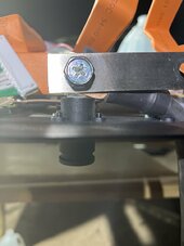
I would not use this battery in parallel with the others, as you now have a MUCH higher resistance long positive cable then the rest will.Only thing I see I don't like is still no grommets or glands where the cables pass through the front panel- DC cables can move when heavy loads are applied suddenly, and long term you could end up shorting the cables on the panel as the insulation abrades...
Was thinking along the same lines. I think the busbar is fatigued at the bend. The pictures show it getting hot there.One thought - I know most wire has a minimum turn radius when passing signals through it, do DC wires have a similar requirement?
Pretty sure the goop was the melted cover over the fuse. The residue won't hurt anything since the fuse looks to be ceramic but I'd scrape it off for neatness sakeI would replace that fuse surely having all the goop leaking out of it earlier from the very high temps has degraded it?
Might be better to bring the positive wire through the other post hole, or just use the post and connect on the outside then a short cable from the inside post to the fuse.Was thinking along the same lines. I think the busbar is fatigued at the bend. The pictures show it getting hot there.
This is a futronics, no copy, but similar idea, and of very good qualityNot sure if mentioned previously, but, this is a copy of an Amphenol Tuchel Radlok connector. I would consider buying the original thing as achieving their rated ampacity relies largely on the quality of their "radsok" crimp sockets which I've personally seen to have mixed quality in knockoff products. Some great, some not so much.
I ended up doing this for all three of the batteries so they are identical. Not sure if that helps the situation?I would not use this battery in parallel with the others, as you now have a MUCH higher resistance long positive cable then the rest will.
This battery will see less demand and provide less current than the others leading to frequent out of balance use.
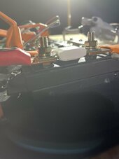
Im off grid so I had to make use of the 2/0 cable I had on handMight be better to bring the positive wire through the other post hole, or just use the post and connect on the outside then a short cable from the inside post to the fuse.
And the re-assembled picture - the negative cable is red outside the case - no confusion becase of the black heat shrink. But what I see is when the faceplate is laid out the cable comes in at an angle through the hole but once the face is up it has a super tight turn radius as well.
I have the 1000A bluesea busbarAnd just as a point of curiosity what is the width and thickness of the busbar?