Nope, the 510 uses 10AWG for all load wires inside the TS, including the L1/L2 gen input, and 8AWG for neutral (pass-through to the gen connection) although it calls for 6AWG connections to the TS.
I did a double take too when I saw that initially, hence the call to Reliance. That's my sample of 1 and vendor support is not always 100% correct so it'd be great if someone else can confirm too!
edit: found this response from Reliance to another customer:
"Hello, thank you for the inquiry and interest in our products!
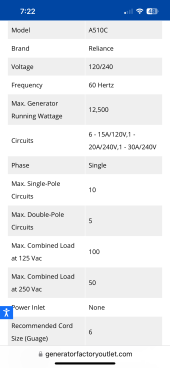
Yes the 50 amp prewired transfer switches like 510C, use 10 gauge wire (90 degree rated insulation) for the short wires that connect to the internal bus bar of the transfer switch.
Electrical contractors are not always in the right, and here is a perfect example. It's unfortunate that wire gauges alone are perceived as being the end-all for ampacity ratings, as it's certainly not the case if one references the National Electrical Code wire ratings. (attached)
Even though the wire we use is actually rated for 40 amps per the NEC table, it really doesn't matter. The factory wiring internal to a control box like this is not subject to general building wire, because it's not. It's a certified product by the testing lab Underwriter's Laboratories Inc. (UL) and whatever wires will pass the heat-rise testing per the national standard for transfer equipment (UL 1008), can be used no matter what the NEC might declare their ampacities are for general use.
In fact if we could pass the stringent heat rise testing with smaller wire, we would use smaller wire. The point is that wires (and along with better insulation) can handle a lot more power than what the NEC will allow for general use, as they force wiring to be overrated in most all general wiring applications. It's quite common that contractors that were taught about wire ratings simply define 12 gauge as 20 amps, 10 gauge as 30 amps, 8 gauge as 40 amps, and 6 gauge as 50 amps, but that is most definitely incorrect. If the wiring was general use (not in a factory built electrical panel), they would have a point and could say that the 40 amp rated wire we use isn't large enough, but that doesn't apply to this scenario. Hope this helps, please let me know if there are any questions, thanks."