diy solar

diy solar

Transfer Switch or subpanel?

Well... I guess this is the official answer from the horse's mouth...

I had contacted Reliance Controls and asked them about using the ProTran permanently in "Gen" mode:

Here is their response:

The ProTran/2 is designed for Generator or Inverter power as a back-up. Not as a main source. It is designed to use a generator or inverter as temporary power.

https://reliancecontrols.com/video-tutorials


I would recommend not using the Transfer Switch but a Transfer Panel like the TRK1003C as a better alternative.


https://reliancecontrols.com/search-result/trk1003c
Interesting. THanks for sharing. I had never even considered this as an issue.
 
I was concerned about running my well pump with other loads when I first installed my pair of EG4 6500EX's. The well pump was the last circuit moved over to the new panel. I had everything moved to the new panel and it worked fine, I ran that for a week or so. I then switched the well pump over and my concerns were unfounded, I've basically ran the house off grid until the last 4 weeks due to low PV yield. If there had been enough PV, it would have remained completely off grid.

I would install a pair of inverters from the start. It will make it easier to run everything now, no rework and additional material in the future plus possibly having to change things.
 
I could do an interlock in the separate critical loads panel for much less expensive
That is what I have done. However I do not yet know if it will pass inspection with my AHJ in California. An alternative would be a transfer switch which could add another $200-500 in costs.
 
I went with a Square D sub panel rather than a Reliance. Cheaper and more options later.
In an “inverter down” situation I could always put in a 50a breaker with transfer lock out in my critical load panel - coming from the main panel. So far it’s been working great powering our chest freezer, fridge, and the whole main floor.
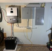
Note - conduit For Solar lines going in this week and I still have some sheet rock and paint to do.
 

Attachments

  • 6CE4A9FE-019B-42E0-821A-ADAFBFBC18B0.jpeg
    6CE4A9FE-019B-42E0-821A-ADAFBFBC18B0.jpeg
    203.2 KB · Views: 36
I went with a Square D sub panel rather than a Reliance. Cheaper and more options later.
In an “inverter down” situation I could always put in a 50a breaker with transfer lock out in my critical load panel - coming from the main panel. So far it’s been working great powering our chest freezer, fridge, and the whole main floor.
Note - conduit For Solar lines going in this week and I still have some sheet rock and paint to do.
@Tripplett did you swing the circuits to the new panel via that raceway at the top? I was considering doing the same when adding a new flush mount panel but raceway underneath panels.
 
Well... I guess this is the official answer from the horse's mouth...

I had contacted Reliance Controls and asked them about using the ProTran permanently in "Gen" mode:

Here is their response:

The ProTran/2 is designed for Generator or Inverter power as a back-up. Not as a main source. It is designed to use a generator or inverter as temporary power.

https://reliancecontrols.com/video-tutorials


I would recommend not using the Transfer Switch but a Transfer Panel like the TRK1003C as a better alternative.


https://reliancecontrols.com/search-result/trk1003c
In spite of someone from Reliance Controls saying this, it is nonsensical to me. When a circuit switch is set to "Line" it connects the load to the wire connected to the original load circuit's circuit breaker from the main panel. If it is set to "Gen" then it connects the load to the hot coming in from the generator/inverter. If it can be permanently in "line" mode, I fail to see why it can't be on Gen most of the time - it just connects the load to one hot wire or the other... and there is absolutely no mention of this whatsoever in the Pro Tran manual. Sometimes the answer you get just depends on which support person you happen to get. ?
 
In spite of someone from Reliance Controls saying this, it is nonsensical to me. When a circuit switch is set to "Line" it connects the load to the wire connected to the original load circuit's circuit breaker from the main panel. If it is set to "Gen" then it connects the load to the hot coming in from the generator/inverter. If it can be permanently in "line" mode, I fail to see why it can't be on Gen most of the time - it just connects the load to one hot wire or the other... and there is absolutely no mention of this whatsoever in the Pro Tran manual. Sometimes the answer you get just depends on which support person you happen to get. ?
I’ve run with 10 circuits on Gen mode for a few years. Works great. Never heard or read where Reliance took that stance. Will continue to do so until I can get another subpanel installed, if ever.
 
@Tripplett did you swing the circuits to the new panel via that raceway at the top? I was considering doing the same when adding a new flush mount panel but raceway underneath panels.
Yep that’s correct. The main panel moved circuits are in the 4x4 inch raceway. 6 total to start, but I have 4 more to do. Used inline Wago connectors. Raceway and Wagos made it easy.

Down below I have 8ga coming from the bottom of the main panel 50a breaker through the 4 outlet box, and landing at the 6xp’s Grid In point. Also this bonds the xp’s ground and neutral bus bars back to the main panel ground and neutral bus bars.

Then 6ga from the xp’s Line out, through the 4 outlet box, and up to the new load panel’s main lugs.

Lastly 12ga wires coming from a 20a breaker in that panel back down to those 4 outlets - gives me quick garage inverter outlets. The deep outlet box also gave me an easy place to route the wires so I figured why not make it outlets.

The conduit coming out of the main panel in the upper right is for an EV charger I put in 4 years ago.
Did you move hots, neutral and grounds or just hot and neutrals. NEC seems to be vague on that topic.
 
In spite of someone from Reliance Controls saying this, it is nonsensical to me.
While I 100% agree, I'm now concerned that if something were to happen that involved my insurance company, they may decline any claim because of the manufacturers recommendation... ?‍♂️
 
  • Like
Reactions: Zwy
While I 100% agree, I'm now concerned that if something were to happen that involved my insurance company, they may decline any claim because of the manufacturers recommendation... ?‍♂️
I hear you - I'm going to roll the dice on this one - since it's not stated in any of their documentation, I think it will be fine. Plus I already have the transfer switch ?
 
  • Like
Reactions: JAS
Did you move hots, neutral and grounds or just hot and neutrals. NEC seems to be vague on that topic.
I went back and forth with people here and local electricians on this. In the end I decided to pull the entire circuits- hot, neutral, and grounds. It wasn’t easy to trace some of those neutrals and grounds either. We worked with mains power off till we pulled those out.

With 6ga bonding the neutrals and grounds from main panel to inverter to sub panel I really didn’t see the need to pull the circuit neutrals or grounds. But there was some questions on gfi circuits at least, so we just did it all. Mechanically I really think the grounds could have stayed but - in for an inch in for a mile I guess.

For the neutrals the connection needs to handle the max it could carry for unbalanced loads. 6ga should have been enough. But… we moved them.
 
The grid isn't a big enough system, and we have to worry about this crap.
C'mon now. There are no perfect systems, any system can fail. The idea is to limit the impact of those inevitable failures to something you can deal with on the rarest of occasions. I don't want to worry every day about this crap, as in things may go south if I fail to do something every day and watch a bunch of stuff. Just needs to work and fail over to the grid without me doing anything when it can't.

I don't have to worry because I built my setup to scale larger easily, I'm going to be able to add panels and batteries easily. At least here, 90KWH bat/24K panels/100A output and It would be extremely rare to kick onto the grid, and not to be a broken record but 100A covers my highest demand 100% of the time. I may get one more inverter to go up to 150A, which is what my mains breaker is now, and add a little redundancy, but I have no worries about leaving town for a week or longer, the system will continue to perform.
 
So how would I (or my wife in my absence) revert to grid when the Inverter takes a sh$t? (Murphy's Law). The only way I know would be either also wire in a transfer switch (more money and more wall space) or start pulling circuits out and putting them back in the main panel (what a PITA). The Reliance subpanel I linked in the beginning does have a transfer switch built in. But, it is between $450-$500 and would not allow me to selectively move circuits from the Inverter to the grid.

I should have also mentioned... Due to location of where I am mounting the Inverter and distance from the main panel, I will not be feeding the 6000XP with AC in from the Grid. Therefore, I need an easy way for us to flip back to grid.

Side note: If I were feeding the AC In of the 6000XP from the main panel, I would not be able to use the ProTran. (It would cause weird neutral/ground loop) and then the subpanel/critical load panel option would be the only safe option.

I kept going back and forth on this (transfer switch vs. critical loads) for my 2 x 6000XP's. While my needs are a little different than yours, one of my primary concerns includes the ability to isolate or bypass the inverters as needed...whether that's for maintenance or an emergency. And considering the system is at a cabin 2.5hrs away, I needed it to be as easy as possible for someone else to flip a switch.

My solution was to first combine the AC output of the 2 inverters then provide a switch to toggle all loads between grid and PV. There are a handful of ways to accomplish this, but I ended up breaking everything out to provide the greatest amount of flexibility. In the end, my system closely resembles this clear diagram by @FilterGuy:


(post #80 on that thread shows a single-inverter example)

Something about that design just clicked and helped make sense of a lot of my initial questions...kudos to @FilterGuy for that!
 
  • Like
Reactions: JAS
I kept going back and forth on this (transfer switch vs. critical loads) for my 2 x 6000XP's. While my needs are a little different than yours, one of my primary concerns includes the ability to isolate or bypass the inverters as needed...whether that's for maintenance or an emergency. And considering the system is at a cabin 2.5hrs away, I needed it to be as easy as possible for someone else to flip a switch.

My solution was to first combine the AC output of the 2 inverters then provide a switch to toggle all loads between grid and PV. There are a handful of ways to accomplish this, but I ended up breaking everything out to provide the greatest amount of flexibility. In the end, my system closely resembles this clear diagram by @FilterGuy:


(post #80 on that thread shows a single-inverter example)

Something about that design just clicked and helped make sense of a lot of my initial questions...kudos to @FilterGuy for that!
You can do the same with an interlock I the sub panel for a single inverter. For two, it's much more challenging because you need two double pole breakers.
 
Inverter combiner box. Or just fuse holders.
Feeding a single interlocked "generator" breaker.
 
  • Like
Reactions: JAS
For sure, but that doesn't meet the "anyone can do it" objective ;-)
Thinking about this more, you could bring both inverters to the panel with their respective wire gauges (6awg?), then use a Polaris connector to 'combine' them into a larger conductors 2awg? that goes to one 100a breaker with an interlock.
 
I pondered this also what I thought about was my experience of trying to walk my wife through getting our media server back online she is getting angrier by the minute. If I'm not home inverter decides to give up the ghost she can go in the garage and flip all the circuits to line on the Reliance Control Transfer switch. Depending on the time of the year I want the solar to power my evaporative cooler, refrigerator, and a battery backup for my computers.
 
Back
Top