diy solar

diy solar

3P, 4S vs 4S, 3P with a single BMS?

soakupthesun

New Member
Joined
Jan 26, 2024
Messages
17
Location
California, USA
Hi folks,

I've done some digging, but haven't found an answer. I'm building my first battery pack, so have a lot of questions...

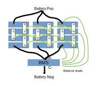
The battery is going to be built from a dozen 105AH EVE cells, 4 in series to make 12v. I have a single OverkillSolar 4S 120 amp BMS. With 12 cells total, the typical arrangement is for the cells to first get wired in sets of three, then the sets get wired in series. 3P, 4S. (Comma added for clarity.)

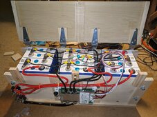
Mechanically, for flexibility in the future, the better arrangement for me might be to have the cells rotated 90 degrees, so there would be three 4S stacks (aimed positive / negative north / south) positioned side by side (east / west). So the wiring is first to have stacks of 4 cells wired in series, then the three stacks get wired in parallel. 4S, 3P. Fat wires of equal length pick up the ends of each of the stacks, connecting them to the BMS on the negative side and to the single post for positive. To use a single BMS for the whole lot, the 3 intermediate connections between the stacks need to be made, connecting the single set of sense wires to those points. I can't use bus bars for this, due to the cell arrangement.

So, the question: Do I need to use really really beefy wires (bus bar equivalent) between the stacks, or can I simply use some 12-14 gauge stranded wires for this? My logic is that since all the cells should be pretty well matched (they are all identical cells, ordered at the same time), there ideally shouldn't be any voltage difference (current flowing) between the three stacks at these intermediate points. In reality there will be some, but the current should only be what is needed for maintaining balance between the stacks, so the thinner wiring should be sufficient.

Yes?

If it helps - and this may be the key - the overall battery will rarely be fully fully charged. Most of the time the battery will sit at around 50% SOC. It will be subjected to light discharge rates relative to its capacity. Current draw will also normally be relatively light, around 10 amps peak on a daily basis, with charging peaking at maybe 15-20 amps for a few hours a day but mostly a lot less than that. I will be enabling the "balance while charging" option on the BMS, and hope that is sufficient. There's a secondary power source in the system that starts kicking in when the battery gets below about 40% (ramping to fully supporting the load at around 20% SoC), so it shouldn't ever go below that except in an extended power outage.
 
Yes, to everything above where you posted "Yes?" 14ga wire between parallel cells is adequate as long as each of the 3 series strings has their own connection to the inverter.

If the battery does not get fully charged (at least to 3.425v per cell) periodically its not going to balance. OverKill BMS may have passive balancing capability only and will not correct large imbalances. Recommend to top balance all the cells first before assembling.
Also recommend adding a 1 or 2A active balancer but only have it turn on once the first cell reaches 3.4V.
 
Can you draw a diagram of how you’re connecting 3 4s strings and that would allow the “balance jump leads” between all cells?

I’m thinking you’d need what 12 or leads? There is the issue of balancing, you want current to flow diagonally across all parallel cells.

IMO it so much easier making 3p packs then connecting them in series, people’s builds and history have supported this.

I have had great success on my 2p4s and JBD keeping it in balance.
 
Thanks for the feedback!

Diagram attached, below. Not to scale, of course, but relatively close. The three thick black wires would be the same length on each side of the battery; planning #6 or #8 wire here. The medium thickness light green are the inter-stack balance wires as discussed in the OP above; #12, and the thin dark green are the balance leads that are supplied with the BMS. Wiring it this way allows me to (carefully!) break the pack into parts for maintenance, without taking the entire pack out of service for a significant period of time. I could also break off two of the stacks and add another BMS for some 24v fun, or ... Lots of options.

The current plan is to assemble the overall pack as diagrammed. Before attaching the BMS I would use my iCharger X8 with its 2A balancer enabled to do the initial top balance of the pack. This is instead of making a 1S12P first, to save the wire that would be required for the one-time event, and precipitated by wanting to mechanically assemble the pack only once so that the cell compression isn't changed.

Mechanically, there would be hardwood planks across the top and bottom, attached together with threaded rods at the ends and between the stacks, to provide cell compression. The BMS would be attached to a lid that spans over the top of the whole mess.

There's a much longer story behind the overall system, and a question. In summary it started life as a way to keep the kitchen fridge cold during power outages, something that used to be a rare event. The initial theory was that I just needed a "big battery" and an inverter, and I could use jumper cables to my wife's SUV to recharge the battery if needed. A 92AH AGM (at the time the largest I could carry) and 2kw inverter were purchased, and that seemed to work but it had significant limitations. Someone offered me a pair of 200w solar panels for cheap, which I hoped would be a better idea than jumper cables. Then figured that I might as well use the panels to remove some of the load on the monthly home electrical bill to recoup their cost - no point having solar panels just sit there in the garage - and you can see how it's all snowballed from there... I should break even by the end of the decade. Or maybe the next one. But no matter; the recent storms reinforced the critical need for a more robust backup power system. We got by but it was close, hence the upgrade of the battery from its current LiFePO4 50AH capacity (which itself was an upgrade from a 20AH AGM) to 315AH, and the solar controller from 20 amps to 30. But realistically I cannot add more panels (space and shading issues), so the while the current battery (a 50AH LiFePO4) does get fully charged daily during the summer, the new one likely will not unless I actively try to do that. So, a question: Given the balancing limitations for the OverkillSolar BMS, how often do I need to get the new pack to full in order to keep the cells healthy?
 

Attachments

  • battery diagram.jpg
    battery diagram.jpg
    34.6 KB · Views: 24
To close this out, I went with the plan above. The iCharger was used with "fast" balancing enabled to do the initial full charge at 15 amps rate. You could see the balancer working to keep everything in line. After the full charge I ran a balance-only pass, followed by another charging pass. This brought all the cells up to around 3.5v, and pretty well balanced. Attached the BMS and finished the build.

With two days of use, it seems to be working well. I am getting some current running across the intermediate balance lines while charging. Mostly very little, but doing some spot checks I've seen an amp or so at times while charging at 15-ish amps overall. Time will tell if the current pattern repeats, but even so the overall balance reported by the BMS remains good (under 10mv) through a couple of cycles, both during charge and after.

The concern about how well the balance will be maintained over extended periods of not being fully charged may be moot, as I found that the OverkillSolar BMS can be set to balance when not charging (which is most of the time). So, I don't need to get the overall system up to the full 14v in order to start the balancing. The BMS balancing may be slow, but it's got plenty of time.
 

Attachments

  • 315AH battery complete, lid open.jpg
    315AH battery complete, lid open.jpg
    382 KB · Views: 22
Time is the key for that Overkill/JBD “balance when not charging”

What sort of load will this battery see? I do wonder how 5-10 cycles will play out.
 
Time is the key for that Overkill/JBD “balance when not charging”

What sort of load will this battery see? I do wonder how 5-10 cycles will play out.
Yeah, I'm wondering the same. I've only had the battery on-line for 2 days now, and so far the balance has remained good. We've got a massive storm coming tomorrow (I'm in California), so this could be interesting on a couple of fronts.

Typical load is about 10 amps, with a "floor" SoC that starts kicking in at around 40-50% provided by a mains-fed power supply. I don't have enough solar to have the system totally off-grid, and I limit the discharge floor in order to maintain some usable power in case of a night-time power outage. Part of the reason for the battery build is to increase that capacity.

The system really has three "seasons". Summer has a strong charging period from about noon to 3pm, with some spotty charging before and after due to significant shading. Typical solar output has been around 1100wh/day, but that was slightly limited by a too-small MPPT controller and not enough storage. Winter is more variable, but seems to average about half of what I get in the summer. Then there's this wonderful but short-lived period that we're in right now where the Sun rises high enough to impart significant power, with the trees that shade the panels in the summer morning and evening not having leafed out yet. With a new MPPT controller and the new battery, the two 200w-ish panels generated some 1.76kwh yesterday, filling the battery and setting a new system record.

So bottom line is that a typical day will see the battery charging to some level during the 3-5 hours of panel sun during the day. Discharge is at up to 10 amps, tapering down until it reaches 40-50% SoC each day; a bit lower if there's no sun for a few days in a row. If the battery reaches 100% SoC on a regular basis I can lower the mains-fed supply voltage a bit to lower the floor SoC, giving the battery a bit more space to absorb the daily solar juice. I didn't really have much room for that with the prior (50AH) battery.
 
OP,

you cannot wire your pack like that with only 1 BMS.

you can't have a bms's balance wire connected to 3 cells that are not in parallel with each other.

You either need 3 BMSs or you need to put 3 cells in paralle first, and then in serises with the other 3-cell packs.

As wired you batteries will not balance and worse, your BMS will not know or report the imbalance.
I honestly don't see the difference; electrically, what I've done should be the same. The cells are fully connected in parallel through the sideways-running wires, and in series with the usual bus bars. The sideways-running wires are certainly lighter gauge (they're #12) than the bus bars, but the current flowing through them is also a lot less, hitting zero as things balance out. I've attached the BMS balance wires to the middle stack in order to minimize any remaining differences that might be present.

All of this has been confirmed with voltage and current measurements on the running system. I'm actually seeing a larger voltage drop between the bolt holding the bus bars to the cells and the bus bar itself (i.e. a voltage across the junction between the top of the cell and the bus bar sitting directly on it), than across the cross-connecting wires. This confirms that the wires aren't affecting the balance process. It's on the order of a few mv, but definitely there. I'm using the bolts and bus bars that were supplied with the batteries. A friend suggested that I insert a copper (specifically) washer between the battery top and the bus bar to get a better electrical connection, but I find it odd that the supplied parts aren't sufficient, if that small voltage drop is even an issue.

Please explain how I've gone wrong. (I'm an electrical engineer, btw, so please be specific.)
 
Looking at the picture, everything seem good to me as the ''big'' wires act as parallel conductor between groups of cells.
So , nothing wrong to only have 1 BMS connect to the cells of the central battery.
 
Looking at your diagram, which 2 other cells is the upper left cell connected in parallel to?
As Yabert notes, the top row of cells are paralleled by the cross-connect wires at their bottom, and the three heavy wires that go to the Battery Positive terminal. Same for the bottom row, which have a set of cross-connect wires at their top, and the BMS B- input at the bottom.
 
Just seems like it’s a complicated solution to an easy problem.

But hey that’s the beauty of this, we all pound that square peg in the round hole when we need to.

Keep us updated on how it does over some cycles.
 
Just seems like it’s a complicated solution to an easy problem.
I thought the same.
Personally I would connect 4 group of 3 parallel cells together with 3 or 6 holes busbars.
Another manner to see this, create 315Ah cell from three 105ah cells.
 
Soakupthesun,

im not the best person to explain this to you .. but putting cells in 3P, 4S is not a straight forward exercise and requires very well matched cells and very low resistance btw cells in parallel so that they stay together in SOC.

In general it's recommended that cells in parallel use double busbars with very clean connections. As wired, you have a lot of resistance btw the cells in parallel, especially on the negative side of the return path.

Lifepo cells have such a flat discharge curve, cells in parallel don't equalize easily in SOC. I have been told they will only do so at the very top of charge curve.
 
The charge curve is logarithmic at the top and bottom. You DO need to charge above 14v to allow such a low current balancer to have ANY effect, particularly on 3 cells paralleled.
With this chemistry, voltage is NOT an indication of SOC. And balancers work on voltage. You can have 2 cells at 3.3 volts where one is at 40% and the other is at 70%
This is alleviated by charging into the log and balancing.
If you are an EE, check best practices. This is not one.
The BMS sees 3 cells as one. There is a not insignificant chance of undercharging one cell and overcharging 2 with the net being what is seen by the BMS.
 
Lifepo cells have such a flat discharge curve, cells in parallel don't equalize easily in SOC. I have been told they will only do so at the very top of charge curve.

The charge curve is logarithmic at the top and bottom. You DO need to charge above 14v to allow such a low current balancer to have ANY effect, particularly on 3 cells paralleled.
With this chemistry, voltage is NOT an indication of SOC. And balancers work on voltage. You can have 2 cells at 3.3 volts where one is at 40% and the other is at 70%
This is alleviated by charging into the log and balancing.
If you are an EE, check best practices. This is not one.
The BMS sees 3 cells as one. There is a not insignificant chance of undercharging one cell and overcharging 2 with the net being what is seen by the BMS.
Ok, thank you both for the details. But to clarify slightly, two cells at 3.3v may indeed have different SoCs, but two cells at 3.300v should be pretty closely matched. I am counting on this with what I have done.

Sounds like the "balance when not charging" option in the BMS is less than optimal in keeping things in balance, since it's inherently doing its work below full charge. It is effective at all, or is this just a bit of glitz that the person who coded the BMS threw in? Watching it for a few days now, it definitely does seem to be effecting things. Right now the battery at an SoC of about 65% and discharging at about 6 amps; the BMS shows 7-8mv balance across the 4 "cells", and the cross-stack currents are in the few-10's of ma. The existence of those cross-stack wires allows me to actually measure those currents via a clamp meter, something which would be difficult with multi-hole bus bars.

Assuming the BMS is actually working, I shouldn't be in any danger of over- or under-charging the cells in the middle of the SoC curve, but I will need to (manually) push the lot to full charge and hold it there for some time every so often. This would correct any cross-stack balance drift that might creep in over time, right? Is this a once-a-year thing, or more often?

The remaining puzzle item is to understand the small cell-terminal-to-bus-bar voltage drops, which are a bit of a surprise to me. First off, is it even a problem? I assume so. Is correcting it a matter of cleaning (and if so what is recommended), or do I need a different mechanical arrangement (e.g. copper washers)?

As a test, I'm going to turn the battery off tonight and see where things are in the morning in terms of any cross-cell currents. In theory there shouldn't be any. Update tomorrow...
 
Assuming the BMS is actually working, I shouldn't be in any danger of over- or under-charging the cells in the middle of the SoC curve, but I will need to (manually) push the lot to full charge and hold it there for some time every so often. This would correct any cross-stack balance drift that might creep in over time, right? Is this a once-a-year thing, or more often?
Correct. Manually balance once-a-year or even less depending of BMS capability and cells quality.
There is no chance that a single cell been out of voltage in your arrangement.
The remaining puzzle item is to understand the small cell-terminal-to-bus-bar voltage drops, which are a bit of a surprise to me. First off, is it even a problem? I assume so. Is correcting it a matter of cleaning (and if so what is recommended), or do I need a different mechanical arrangement (e.g. copper washers)?
It's because cells in parallel can have differents characteristics.
An extreme example: You have three cells in parallel. Two 105Ah cells have internal resistance higher than the third cells in parallel.
Now pull 100A from the battery and instead of having 33.3A from each parallel cell, you will maybe have 25A from the two cells with higher resistance and 50A from the third cell. That way, there is of flow of current who will pass by the parallel wire instead of the busbar.

or do I need a different mechanical arrangement
To me, the best arrangement in your case is to connect 3 parallel cells together with a 3 holes busbars. That way the cells always stay balanced and act as a 315Ah cell.
But I think your arrangement will work fine. And the best is you will be able to pull a big load and measure current between cells with a clamp meter over the ''small'' black wire to know if there is a flow of current between cells.
Right, but that imbalance in currents can be created in more than one way. Instead of a high impedance cell, for example, imagine that all the cells are exactly matched but the connection between one cell and its busbar has some resistance. In that case, that same "sideways" current would flow. I'm coming to the realization that the busbar to cell connection is where the trouble starts, so rebuilding my battery in the more traditional arrangement wouldn't actually solve the problem. In fact, because there's no opportunity to run a clamp meter around the busbars, I'd never know that there was a problem. Even if you could, the imbalance current would be swamped and invisible under the load current flow. But it would still be there. My arrangement does have more connections (more opportunity for connection failure), but at least the issues can be measured and addressed. With good busbar-to-cell connections, the current that flows on my wires should be minor and resolve itself with time. I could even argue that the small resistance of my cross-connect wires forces the primary current flow to remain within each stack; presume that's a good thing?

Letting the battery sit last night with nothing going in or out confirmed that each member of the sets of three cells that are connected with the wires had balanced out to exactly the same voltage (out to 4 places in precision). The BMS was already happy with the 8mv balance top to bottom, so nothing changed there.

So back to the cell-to-busbar connection... The as-supplied configuration has the busbar sitting directly on top of the cell terminal, with a split washer on top, and a bolt going through the pair to hold them together. I've tried a few combinations of additional washers (regular or star) with no improvement. What is the best practice here?
 
Determining “Balance” when the cell voltage is 3.4 or under it’s kinda pointless.

Some load cycles will really tell you how it handles.
 
Back
Top