MrPablo
Solar Enthusiast
Nothing is jumping out there, perhaps try connecting to the ESP32 and getting live logging at some point, no rush.
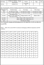
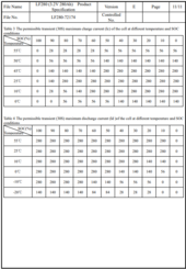
EVE LF280K's here:It's definitely feasible, do you have any good reference for C-rate vs temp?


Interesting.. I think I remember seeing a video of someone trying to charge one well below zero but I don't remember the outcome.This is correct. At low temperatures, the increased internal resistance will automatically prevent high C rates.
Yup check out your datasheet. Even if low temperature IR will compensate for high C rates I don't think this will hold true at higher temperatures. IMHO temperature compensated dis/charging limitations can't be a bad thing!I didn't realize *that* much derating is required...
Based on @upnorthandpersonal analysis I thought that no derating (at very low temperatures !) was even necessary, since you'd just need an extreme voltage to be able to push that current.
In my case batteries were sitting at around 10-20 °C this winter and charging up to 100A (280Ah). So *barely* within limits...
Each battery in my system is sized (breakers, cables, ...) for 100A RMS only. So you could say that the margin is "built in" in my case (unless I try to charge below 0°C, but BMS won't let me do that).
AFAIAA the "requested" charge voltage actually defines a "max" charge voltage. The actual voltage generated by the Solis will be the voltage required to create the requested charge current, up to the specified "max" voltage. Obviously the voltage that Solis will deliver will depend on the voltage of the battery and the resistance of the wires to deliver the requested charge current.Solis inverters don't seen to respect the requested charge voltage correctly when using the Pylontech protocol. This can result in lower or higher battery voltages than requested.
Yes it is Perfect at this stage - working as expected
you read my mind on the topic of the Solis protocol - I basically just finished testing User-Define protocol option from the Solis inverter, it worked fine except it did not allow me to change the Overdischarge SOC below 20 .
It was stock on 20, so I have gone back to using the Pylontech protocol - yes i know the values seem very low, but i had to set it low to get more capacity out of my system as at 20% there is still a lot left in the Batteries, so i use the JKBMS to control the Overdischarge SOC instead (keeping it at the operational values set on the Growatt GBLI5001 Datasheet)
View attachment 201519
I know - currently i am telling the system to stop at 5% if it fails to do so and it goes below - charge again from the below 4% value to a 5% Resting SOC. - thats o.k with me.I think you will find that the OverDischarge SCO % simply cannot be set lower than the ForceCharge SOC %. And likewise, the ForceCharge SOC % cannot be set higher than the OverDischarge SOC %. Hence, the order in which you set them is critical.
o.k...i get your point thanksGreat. Just be aware that once OverDischarge SOC% is reached, the Solis will (obviously) stop using the battery to supply the house load... BUT, about 30W will still be consumed by the Solis to power its internal electronics. Therefore, depending on the size of your battery, the SOC will still drop. Mine will drop about 1% per 3 hours with a 14kWh battery pack.
Therefore, if your ForceCharge SOC % is only one percent lower than the OverDischarge SOC value, you will find that charging from grid will kick in sooner. IMO it is better for the two values to be a bit further apart if you want to avoid grid charging.
That's what I expected the inverter to do, but my results didn't always match.AFAIAA the "requested" charge voltage actually defines a "max" charge voltage. The actual voltage generated by the Solis will be the voltage required to create the requested charge current, up to the specified "max" voltage. Obviously the voltage that Solis will deliver will depend on the voltage of the battery and the resistance of the wires to deliver the requested charge current.
That's all very interesting, thanks. Was thinking about a 17s implementation, but my Solis specify DC range of only up to 58V.That's what I expected the inverter to do, but my results didn't always match.
If I set the requested voltage to 58.7v (I run a 17s pack) and the pack was being fully charged (off-peak overnight, etc), then the Solis would supply up to 60.2v (inverter DC voltage via modbus), giving 59.5v at the BMS.
Other times, it would settle at 58.7v at the inverter, so 58.3v at the battery. I calibrated the BMS, but I can't see a way to calibrate the Solis.
As soon as I changed to the SMA protocol with SMA battery name, using AoBo on the inverter... it behaves itself.
The inverter will supply the required voltage to get the battery to 58.7v at the BMS. Overshoots have been reduced to 0.1v at most.
It's a guess, but I think Solis + Pylontech profile results in the inverter referencing internal DC voltage vs requested voltage.
On SMA / AoBo at least, it seems to reference BMS voltage vs requested voltage.
I've seen the same behaviour on a couple of other Solis inverters - perhaps that's part of the reason for Pylontech OV warnings when using a Solis.
17s is definitely feasible on the RHI and EH1 inverters. Max charge voltage can be set to 60v, inverter overvoltage protection is 62v max.That's all very interesting, thanks. Was thinking about a 17s implementation, but my Solis specify DC range of only up to 58V.
Interesting about the differences with the PylonLV profile. I use the user-defined profile, which responds to standard SMA CANBus comms OK. Then there is clearly something odd with the Solis implementation of Pylontech protocol.
Just for reference... Right now I am facing this issue on my temporary cabling setup.@Der_Hannes, @Sleeper85 : do your code also handle the transition from / to CC (Constant Current) and CV (constant voltage)? Right now I have a charger connected in parallel to the battery and to charge at full speed (force it into CC) I have to set the "reference voltage" to 58V or so (then it will work in constant current mode). Of course I'll habe to reduce that as I near the float voltage and the absorbtion voltage especially.
But is this something your code does or is it something that the inverter or my charger controller has to do?
The inverter will be responsible for transitioning from CC to CV, the code will continue to request charge voltage until it meets the conditions for float.Just for reference... Right now I am facing this issue on my temporary cabling setup.
For instance 16mm2, 10m each way (20m loop) yields approximatively 20mOhm wire resistance. 2 such set of wires in parallel and 2 chargers. So basically 10mOhm overall.
Actually a bit more due to fuses breakers, etc.
So at 100A it takes approx 1V to compensate that.
Put another way: if I don't put at least 1V more that needed on the reference voltage, the charger doesn't deliver the full current and operates instead (from its point of view) in constant voltage mode.
As I said it's temporary. 2x16 mm2 on each polarity. Or otherwise said each charger 50A on a 16mm2 wire. Plenty.The inverter will be responsible for transitioning from CC to CV, the code will continue to request charge voltage until it meets the conditions for float.
16mm² seems small for 100A, I use 25mm² for my setup and in hindsight, should have gone to 35mm².
I completely missed that you have double wiring, my mistake!As I said it's temporary. 2x16 mm2 on each polarity. Or otherwise said each charger 50A on a 16mm2 wire. Plenty.
Internal to the batteries it's hugely oversized. 50mm2. Next time I'll go with 35mm2 for 100A...
So I should I simply set charge voltage to 58V and then let it drop once approaching OVP?
Take care of your little "project"I completely missed that you have double wiring, my mistake!
If your separate charger is set to 58v, when the ESP32 wants to go into float mode, the separate charger will try and maintain the max charge voltage won't it?
I'm slightly sleep deprived due to a 3 month old baby so I might have missed this, is the separate charger another inverter?
Perhaps the best option is to force the grid charger to follow the requested voltage, you can definitely use MQTT to get these (or HA if you use that).Take care of your little "project".
No inverter is only doing solar MPPT, charging battery (only from solar!) and off grid supply (island mode).
Charger is grid connected and only charging batteries.
Right now the charger is just working in voltage mode based on a excel table.
But long term I also will need to do it more intelligent. That's why I'm trying to figure out if I should just follow what the Esp32 says.
The other option is of course to apply full blast voltage and, once the MEASURED voltage rises above the required level (either on the charger or battery side), reduce it.
I'd just like to avoid developing a whole separate controller (like I was about to do / doing) if all I should focus on is rather just e. G. grid power control based on lowest cost (only take care of the energy "strategy" and leave all the control in the hands of the Esp32).
EDIT: and of course if my charger should just follow the Esp32, then I can just get the value from Mqtt or influxdb and change the charger voltage
Yeah, that was my plan (although using @Der_Hannes setup since I have multiple batteries)Perhaps the best option is to force the grid charger to follow the requested voltage, you can definitely use MQTT to get these (or HA if you use that).
If needed, just apply an offset so that the grid charger is set to 'requested charge + 1.0v' or so. If you also have the ability to adjust charger current, you could also follow requested charge current.
If the PV inverter is also connected via CANbus, you'll have automatic control on both power sources and a pretty impressive setup.


