diy solar

diy solar

Grid Tie and off Grid

ddmbr

New Member
Joined
Aug 10, 2023
Messages
36
Location
UK
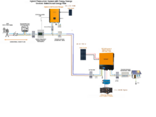
I have 20 panels in an off grid setup ie acinput from the grid, ac output to the breaker unit/consumer unit which feeds the load as well as 8k of panels and 30kwh of batteries. Being in nothern europe sun is scarce from nov - feb but the spring/summer months I get more solar than I need so I was thinking of adding grid-tie into the mix as I have an extra 10 panels lying around which I havent hooked up to the off grid as yet and thought might be worth having these feed the grid and at least get something back from the utility. My vendor told me this would damage the inverters. The design I sent to them attached below. What I cannot understand is why it would damage the inverters?
1710338050048.png
 
I do not see a problem with your proposed setup, at least here in the states.
I have 2 grid tie systems and 1 off grid system, in a similar setup
where some people have a problem is when they are wanting to put the AC output from the off grid inverter into a panel that also has the grid on it. cant do that
you have a dedicated off grid breaker panel and should be fine
 
Thats what I thought, from my understanding the off grid would be just another circuit in the grid tie breaker panel.
 
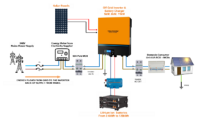
What I have now is considered off grid design but with grid backup as below.

Effectively my proposed plan is to move the ac input from a direct connection to the meter to a breaker in the grid tie panel.


1710347487888.png
 
That is grid-tie not off grid, there is a direct connection to the incoming meter and hence the grid.
 
Just to clarify I have an off grid inverter with the ac input connected to the grid for backup. I have 10 spare panels and rather than add them to the off grid inverter system I had the idea to disconnect the ac input of the off grid inverter. Then I would install a grid tie inverter connected to a new breaker panel with a 63amp breaker circuit that I would then connect to the ac input of the off grid inverter. THe house load breaker would remain connected to the output of the off grid inverter. The chassis ground for each system would move accordingly.

In terms of frequency shift; assuming I understand you correctly the ac input of the off-grid inverter is currently connected to the grid as a "backup" power source and supports frequency fluctuations.
 
It may be called an off grid inverter but if it has a connection to the grid then its Grid-Tie and needs G98 for 3.68kw or G99 above 3.68kw application to the DNO.
 
When you are grid connected, the AC Coupled circuit can put out all the power it can produce because you have the grid to feed back to.
If the grid is down, your inverter will produce the frequency needed for the AC Coupled circuit to run. If it produces more than is needed it could be a problem.
 
In the UK any inverter connected to the Grid has to be of Grid-tie design and have G98/G99/G100 type approval. Does not matter if its off grid or grid-tie, if its connected to the grid its has to have type approval.
 
That really doesn't mean what you think it means, and you are just confusing people by using terminology in easily-misunderstood ways. it's going to be hard to get an answer about "An off-grid, grid-tied inverter, by which I mean ...", when everyone first has to wrap their brains around what you are talking about.
 
On the advice of the vendor I wont be pursuing it in any case and will stick to my "off-grid" design. Thanks all.
 
What I have now is considered off grid design but with grid backup as below.

Effectively my proposed plan is to move the ac input from a direct connection to the meter to a breaker in the grid tie panel.


View attachment 201906
As UK registered MCS installer, Electrician and Napit certified person, a few things to point out in your diagram above, You can't have a 63A MCB from the DNO cutout to your inverter with zero protection in place. You normally have the supply concentric cable from the DNO to the cut out, usually 80/100Amp main fuse on a TN-CS / PME supply combined Earth & Neutral (most common in the UK) where the Earth/ Neautral is split out and connected to the MET then on to your consumer unit. You need at least an RCD/RCBO rated for the full current your supply / load can demand for safety reasons, if you were to have any fault on the incoming supply, PEN fault, lost neutral etc the whole of your inverter casing could potentially become live, and that in your diagram is the main first point of incoming supply with zero protection and is against all UK BS7671 Regulations, you Also need SPD to the main prior to the inverter fed back to the MET. Secondly, you will not recieve any export payments unless you have a valid EIC, Part P, DNO & MCS certificate in place from a registered installer, CPS and or Electrician. You also show what looks like an Earth electrode on the inverter incoming supply but not back to the MET for the PME supply which could leave floating Earth for any grounded or bonded pipework in the property or extronious metal parts within your property should there be a fault from your supply or a neighbours on the same phase.. You also have no Earthing arrangment from the consumer unit post inverter supply bar the second Earth Electrode on the property diagram. You will also need DNO pre approval G99 for anything you connect to the grid prior to installation with all equipment grid connected needing ENEA approval.
 
@shavermcspud

These are not technical installation diagrams by any means and are to just demonstrate where the different systems sit to help frame my question for the forum; which was to ascertain why the vendor said it would damage the inverters which I didn't feel was explained clearly. I've no plans to move ahead in any case as my vendor did explain it wouldn't be worth the installation cost to have an MCS installer such as yourself to do the necessary paperwork and install vs the minimal payment from the utility per year.
 
Back
Top