diy solar

diy solar

JK-BMS-CAN with new Cut-Off Charging Logic (open-source)

My bad, accidently commented that part out. o_O

Debug is gone, and now these [W] arnings caught my attention.

21:39:51[W][component:232]Component esp32_ble took a long time for an operation (127 ms).
21:39:51[W][component:233]Components should block for at most 30 ms.
I always have those ones not sure how bad it is ...
 
My bad, accidently commented that part out. o_O

Debug is gone, and now these [W] arnings caught my attention.

21:39:51[W][component:232]Component esp32_ble took a long time for an operation (127 ms).
21:39:51[W][component:233]Components should block for at most 30 ms.
Sometimes the problem is between the chair and the screen ;)
 
Here is the new code regarding the calculation of SOC.
Keep in mind that this code should work can import the battery chemistry used LFP, Li-ion or LTO so it cannot use a fixed voltage value as you suggest.
Furthermore I don't want to change the SoC of the JK-BMS too much, when JK-BMS is well calibrated it is not so bad.

The code below will send the actual SOC of the BMS(s) from 1 to 98%
Only 0% and 100% are corrected to correspond to reality.

YAML:
  # +--------------------------------------+
  # | Battery State of Charge (SOC)        |
  # +--------------------------------------+
  - platform: template
    name: ${smart_bms_name} Battery SOC
    id: ${smart_bms_id}_battery_soc
    unit_of_measurement: "%"
    device_class: battery
    update_interval: ${smart_bms_update_interval}
    lambda: |-
      float soc = id(${smart_bms_id}_state_of_charge).state;
      float min_cell_v = id(${smart_bms_id}_min_cell_voltage).state;
      float cell_uvpr = id(${smart_bms_id}_cell_uvpr).state;
      if (min_cell_v <= cell_uvpr) return 0;                       // Real 0% Sending 0%
      else if (soc < 1) return 2;                                  // False 0% sending 2%
      else if (soc < 99) return soc;                               // SOC < 99% => Sending BMS SOC
      else if (id(${smart_bms_id}_eoc) == true) return 100;        // End Of Charge => Sending 100%
      else return 98;                                              // Otherwise => Sending 98%
1.: Thanks @Sleeper85, Actually, I used this approach for both ends but using 98 and the minimum SOC (not 2%) to reflect the SOC cut-off level needed for the Inverter to stop charging (.i.e Cut-off/ On-grid EOD set at 20% but JK SOC is lower when minimum cell voltage is still 3.1V or more, the SOC reporting to Inverter shall be kept at 21% till min cell voltage goes below 3.2 or 3.1 depending on user's prefer cut off voltage level). If I dont change the SOC at the EOD SOC, inverter will stop discharging when cell voltage is still high enough.
So the SOC changes is only at ends not during the charge/discharge process!
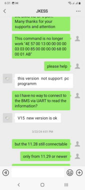
2.: MultiBMS: I have 2 battery (one with JK-BMS and one with Huawei brand (different BMS from Huawei). I wired them in parallel and have just an additional slider for defining the capacity of the battery in parallel. This will help regulating the total charging current limit sent to the Inverter. It would be better if we can monitor current at other battery but I found that my Lux inverter does have internal shunt for both voltage and current so I don't need to make it become more complicated. Principally, we can do wire connection (also require to keep the JST interface be longer) to several BMS using Software serial but the returning value is not much (only data about cell, alarm) while what we need is to control charge/discharge well enough. My recent observation is: new JKBMS Soft Version 11.36 and higher (11.XW) does not allow UART command query anymore (image from JKBMS technical staff).
1712187167726.png1712187200696.png
They recommended to upgrade to V15 but does not share further information at all.
Many thanks for your sharing!
 
Last edited:
Thanks @Sleeper85, Actually, I used this approach for both ends but using 98 and the minimum SOC (not 2%) to reflect the SOC cut-off level needed for the Inverter to stop charging (.i.e Cut-off/ On-grid EOD set at 20% but JK SOC is lower when minimum cell voltage is still 3.1V or more, the SOC reporting to Inverter shall be kept at 21% till min cell voltage goes below 3.2 or 3.1 depending on user's prefer cut off voltage level). If I dont change the SOC at the EOD SOC, inverter will stop discharging when cell voltage is still high enough.
So the SOC changes is only at ends not during the charge/discharge process!
Many thanks for your sharing!

How did you calibrate your BMS?
 
How did you calibrate your BMS?
I use multimeter to do the work when charging at current above 2A on both voltage and current. Then set the calibrated value once only. The rest is to keep the charge prolonged to bring the battery voltage as high as 3.45*16 and as low as 3.2*16 while maintaining delta voltage be lower than 150mV by reducing charge/discharge current limit!
Maybe, the approach that I am pursuing is different from yours but it make SOC link as much as possible to cell voltage at 3.2 and 3.4 or 3.45 point.
Charging voltage applied at the inverter is: 3.45*16 or 3.5* 16 depending on case (quality of battery cell)
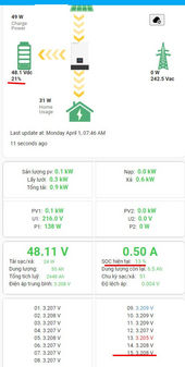
To give more evidence on this, please see the attached image
1712187745742.png
When min cell is above the set level of 3.2 but soc fall below the EOD level (20% set by user at inverter side to allow inverter to cut off. I made also an automation to sync Inverter EOD SOC with esphome via GuyBW's integration for Luxpower Inverter), ESP32 will report the EOD level + 1.
1712187883964.png
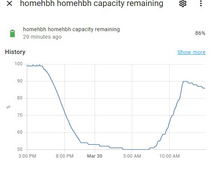
But this one have JK SOC still at 50% when min cell is already 3.2V (discharge current is only 3A). So it should be safe if we stop discharging when SOC is at this high!
Using this approach will leave us not busy with matter of SOC inaccuracy why can still do a little with control on voltage (even this is not quite accurate as well when cell voltage is not open circuit voltage - OCV)
 
Last edited:
I use multimeter to do the work when charging at current above 2A on both voltage and current. Then set the calibrated value once only. The rest is to keep the charge prolonged to bring the battery voltage as high as 3.45*16 and as low as 3.2*16 while maintaining delta voltage be lower than 150mV by reducing charge/discharge current limit!
Maybe, the approach that I am pursuing is different from yours but it make SOC link as much as possible to cell voltage at 3.2 and 3.4 or 3.45 point.
Charging voltage applied at the inverter is: 3.45*16 or 3.5* 16 depending on case (quality of battery cell)
To give more evidence on this, please see the attached image
View attachment 206865
When min cell is above the set level of 3.2 but soc fall below the EOD level (20% set by user at inverter side to allow inverter to cut off. I made also an automation to sync Inverter EOD SOC with esphome via GuyBW's integration for Luxpower Inverter), ESP32 will report the EOD level + 1.
View attachment 206866
But this one have JK SOC still at 50% when min cell is already 3.2V (discharge current is only 3A). So it should be safe if we stop discharging when SOC is at this high!
Using this approach will leave us not busy with matter of SOC inaccuracy why can still do a little with control on voltage (even this is not quite accurate as well when cell voltage is not open circuit voltage - OCV)
When you calibrate voltage on the JK BMS you MUST do it a NO-LOAD: ZERO CURRENT. Open the breaker / disconnector / disable charge and discharge. Let them settle for a while. Then calibrate the voltage measuring with a trustworthy multimeter.
 
When you calibrate voltage on the JK BMS you MUST do it a NO-LOAD: ZERO CURRENT. Open the breaker / disconnector / disable charge and discharge. Let them settle for a while. Then calibrate the voltage measuring with a trustworthy multimeter.
Hi,
This is not for OCV or totally rest calibration. It is current calibration for JK to measure correctly! Both current and voltage are needed for Coulomb counting to work effectively. What I am focusing on is how to make JK work most effectively!
Best!
 
Hi,
This is not for OCV or totally rest calibration. It is current calibration for JK to measure correctly! Both current and voltage are needed for Coulomb counting to work effectively. What I am focusing on is how to make JK work most effectively!
Best!
Coulomb Counting is only Current. Coulomb = Current x Time [As] :) .

Voltage is more used to calculate Power (Voltage x Current) and determine end of Charge / Discharge (OVP / UVP).

EDIT 1: from your previous post, it rings familiar ... for a 16s LiFePo4 battery it stated I had 68% SOC / Capacity Left when the voltage was just 52.0 VDC ! In my case that was due to never bringing the cells high enough (voltage) and for long enough (time) so that they would effectively be fully charged and the SOC algorithm would correctly reset (same way as Victron Smartshunt: voltage > threshold e.g. 55.2 VDC, current < threshold e.g. 0.5% of Capacity Value in A, time > e.g. 10 minutes). Andy from Off Grid Garage made a great video about the Victron Smartshunt and how it works. I believe the JK BMS works in a very similar way (as the physics are the same).

 
Yesterday I was successful in getting the BLE version to work, but today the cable version is struggling for me.

My hardware = B2A20S20P-Heat-CAN, Atom S3 Lite on the CA-IS3050G.

can_tx_pin: GPIO5
can_rx_pin: GPIO6
tx_pin: GPIO1
rx_pin: GPIO2

All output I can see is more or less this, ( repeating )

00:37:26[D][esp32_ble_server:155]BLE Client connected
00:37:26[D][esp32_ble_server:164]BLE Client disconnected
00:37:30[D][esp-idf:000]E (185943) BT_HCI: CC evt: op=0x2022, status=0x2

Anyone :unsure: ?
So you are using one ESP32 for each connection or trying to combine into 1?
In case you are using 1: you need to be sure that the wire connection is made to a JK with firmware version is earlier than 11.28. Later than this, you will have to upgrade firmware to Version 15 (as told by JK engineer).
 
Yesterday I was successful in getting the BLE version to work, but today the cable version is struggling for me.

My hardware = B2A20S20P-Heat-CAN, Atom S3 Lite on the CA-IS3050G.

can_tx_pin: GPIO5
can_rx_pin: GPIO6
tx_pin: GPIO1
rx_pin: GPIO2

All output I can see is more or less this, ( repeating )

00:37:26[D][esp32_ble_server:155]BLE Client connected
00:37:26[D][esp32_ble_server:164]BLE Client disconnected
00:37:30[D][esp-idf:000]E (185943) BT_HCI: CC evt: op=0x2022, status=0x2

Anyone :unsure: ?
Are you sure tx/rx is not reversed? Did you connect the GND wire on the jk bms port to somewhere in your esp32?
 
So you are using one ESP32 for each connection or trying to combine into 1?
In case you are using 1: you need to be sure that the wire connection is made to a JK with firmware version is earlier than 11.28. Later than this, you will have to upgrade firmware to Version 15 (as told by JK engineer).

Ooh, well then that's probably it.

the BMS seems to have hardware version V11.XA and software version V11.43. Boooh.
 
So you are using one ESP32 for each connection or trying to combine into 1?
In case you are using 1: you need to be sure that the wire connection is made to a JK with firmware version is earlier than 11.28. Later than this, you will have to upgrade firmware to Version 15 (as told by JK engineer).
Would you mind pointing me in the right direction on how I can move forward in updating the firmware to v15?
 
Would you mind pointing me in the right direction on how I can move forward in updating the firmware to v15?
You can check here, he made details guidance and resource included then!
The guy from JK-BMS (engineer informed me that it needs to update to V15 but he provided no further information). I have tested this yet. Better using https://github.com/syssi/esphome-jk-bms/blob/main/esp32-ble-example-multiple-devices.yaml
This allow the ble to poll several BMS using a single ESP, I tested and it worked!
 
Last edited:
A bit side topic but ... How do you manage to get OTA working ?

I tried several approaches and none works so far :(

a. Using esphome run XXX.yaml -> This results in timeout failure during upload or similar other messages.
GitHub Issues and Home Assistant Forums seem to point to a Network Issue.
I am running this off a Rock 5B using hostapd and an Alfa AWUS1900 USB-Wifi Adapter (RTL8814AU).

b. Running esphome dashboard in a Podman Container (similar to Docker) doesn't really work.
I cannot do anything since autodiscovery doesn't work. If I add devices manually, there really isn't a "Firmware Upload" button or something similar.

c. Running esphome integration for Home Assistant I can see entities etc, but I cannot upload a new firmware.

d. Web Server does NOT support OTA on esp-idf framework (only on Arduino) according to documentation.
We are using esp-idf framework here ...
 
Last edited:
A bit side topic but ... How do you manage to get OTA working ?

OTA would only work after I had the Atom connected to my Wifi & assign the ( in my case ) jk-bms-can.local ( I edited hosts file ) to the ip of the wifi connected atom ( 192.168.x.x ).

esphome assisted me in flashing a firmware that would successfully connect to my wifi in the first place.

https://web.esphome.io/?dashboard_install
I have my own DNS Server running so the DNS Record is correctly resolving to the IP Address (Static Lease on the DHCP Server) of the ESP32.

The problem is that the upload never goes past 10%. Sometimes it fails at 4%. Sometimes it gives up just after starting the upload process.

I also tries to restart the ESP32 in Safe Mode prior to OTA. Nothing :rolleyes: . The only thing that wants to work is a reliable USB cable :rolleyes:.
 
Back
Top