diy solar

diy solar

Live Ground Shocked 5 Year Old

If everyone reads the first post.

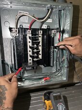
OP states he is reading 120V between hot and ground.

This is correct.

He says that the breaker feeding the hot was off, and he STILL reads 120V

This is wrong, and dangerous.

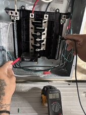
What OP does NOT ever state is what the child was shocked by touching.

Nor does OP say much other than with the box disconnected from the container, there is no more shock.

I would like a post stating measurement facts.

1. What meter reading is reached between Neutral, and the container wall.

2. What meter reading is read between container wall and the ground connection.
Both Volt reading, ac AND dc, and an ohm reading IF and ONLY IF the volt readings are zero.
 
Grounding conductor should never pass through any metal enclosure. (Inverter, service panel, junction box, wireway)
It should be connected to all conductive parts. This makes these parts safe to touch.
But, that's only true if the grounding system is actually bonded to the electrical system. (N/G bond)
The grounding system is created by and begins at the N/G bond.
Which takes us back to my first post in this thread.

"Short answer.
Your system is not properly grounded.
You don't have a N/G bond."

The fact that the wrong (European) version of Growatt was used, would not have caused the shock. (If the system was properly grounded)
Because it would have never powered up, in the first place.
 
@Joshua787 OK, thanks. Could you use a multimeter to verify which pin on the jumper power cord actually connects to shipping container? Also check if plug pins are correctly wired to 2nd outlet.
outlet.jpgplug.jpg
 
Correct

Not the same conductor.
The European neutral is your L2 hot. This needs to be unbonded.
Your split-phase neutral from the transformer needs to be bonded.
THANK YOU SO MUCH!!!! I removed the bolt and it worked!

You said "Your split-phase neutral from the transformer needs to be bonded." How do I do that? do you think this would solve the problem below?

NEW PROBLEM:
Im experiencing Voltage Leakage. When the 20A breaker is ON it reads 81V instead of 120V when I measure from Ground to Hot (See pics)

When the 20A breaker is OFF - i measure 33V from Neutral to Ground and 18V from Hot to Ground.
 

Attachments

  • off 20v g2H .jpg
    off 20v g2H .jpg
    119.6 KB · Views: 16
  • N2G 33V.jpg
    N2G 33V.jpg
    141 KB · Views: 15
  • oOn H2G 81V.jpg
    oOn H2G 81V.jpg
    114.8 KB · Views: 15
  • D7F0B7AC-D4E8-4CC3-A29B-E352C7FB5671_1_105_c.jpg
    D7F0B7AC-D4E8-4CC3-A29B-E352C7FB5671_1_105_c.jpg
    116.6 KB · Views: 16
@Joshua787 OK, thanks. Could you use a multimeter to verify which pin on the jumper power cord actually connects to shipping container? Also check if plug pins are correctly wired to 2nd outlet.
View attachment 207065View attachment 207068
The green wire was grounding the box to the second outlet. this was done by striping the wire and wrapping it around the self tapping screw that attaches the box to the shipping container. i left a tail on the ground wrapped around the screw that is wrapped around the ground screw on the outlet.
 
Great! Now with inverter NG bond screws removed you need to create neutral to ground bond in your right panel. Connect with a piece of wire as shown in blue. Connect ground wire to your container to make sure it never goes hot again. Connect ground wire to ground terminals of both inverters.

NG bond.JPG
 
NEW PROBLEM:
Im experiencing Voltage Leakage. When the 20A breaker is ON it reads 81V instead of 120V when I measure from Ground to Hot (See pics)

When the 20A breaker is OFF - i measure 33V from Neutral to Ground and 18V from Hot to Ground.

Probably no neutral-ground bond. There is capacitance, and DMM measures voltage divided by capacitors in series.

It sounds like you isolated inverter "N" (one of your "L") from ground. You said "bolt", but I suppose you mean a screw through inverter PCB into chassis; that was all the rage a few months back.

You would ideally have a detailed schematic, maybe made with photos of equipment taken from websites, showing all wires L1, L2, N, G connecting everything. Also showing any (typically green) bonding screws which are used in breaker panels to connect Neutral bar to box for use as combined neutral and ground.
So far your photos have shown wires passing through some boxes. All need chassis ground.

You may get it apparently working but still have latent safety issues. Ungrounded boxes could become shock hazards in the future, if not grounded so a fault causes inverter to shut down.
 
I would also bond solar panel frames together and connect them directly to ground rod via dedicated #6 solid copper direct ground wire. Also connect shipping container to same ground rod via it's own wire for redundancy. This way if your solar panel frame gets struck by lightning it will route strike current direct to ground rod instead of traveling through that original ground wire in your conduits.
 
Last edited:
NEW PROBLEM:
Im experiencing Voltage Leakage. When the 20A breaker is ON it reads 81V instead of 120V when I measure from Ground to Hot
Did you consider reading the replies with a focus on comprehension and MOVING the ground-neutral bond from the wrong place to the right place?
 
I take that to mean she was standing on the ground and touched outside of container.
Yea I think the shock was superficial due to capacitive coupling between components. Inverters were ungrounded and floating.
 
You said "Your split-phase neutral from the transformer needs to be bonded." How do I do that?
There are a few ways to accomplish this.
But basically the neutral and ground need to be connected together.
A piece of green wire will between the two bars is a simple way.
 
So inverter output tied to chassis.

But there was a ground rod, I think. Not sure what connected to.
I'm not confident that shock current was limited by capacitance. With all the wires and connections or lack of them, a source of hazardous current may be present. Or not. Current could have been limited by rubber shoes (what I usually, but not always, have "experienced".)

Your suggestion of a light bulb (did you plagiarize that from me?) shows if there is a hard path, but of course isn't sufficient to distinguish safe current from hazardous.

I've suggested light bulb to see if a cheap inverter could have neutral bonded, or was 60/120V split-phase.
 
These days I have to clarify "incandescent", since without understanding they're likely to grab a "light bulb" which doesn't accomplish our measurement objective.
 
Back
Top