diy solar

diy solar

Portable Victron Power Station operational

I think the UL listed ones have a taller wire box to give you more room. But then it's bigger overall and you are trying to be compact.
 
In my opinion Victron took a giant step backwards when they opted for the flexible input wire covers on the Multiplus II. They are flimsy and easily move out of place unless placed just right. The original Multiplus had a screw down version which in my personal opinion was much better designed.

IMG_3817.jpegIMG_3818.jpeg
 
With this build there will only be one battery and one Multiplus. It is commonly recommended to use a precharge resistor to allow the capacitors on the Multiplus to fill, avoiding strain on the Multiplus and battery BMS.

For this build I will be using an approach demonstrated by Current Connected. Very simple and reduces the chance of a mistake:


IMG_3833.jpeg
 
It is a standard 12 gauge extension cord. Meant for a standard household circuit. The 6 awg from the junction box is to ensure the wire fits snugly in the Multiplus II. A revised version since this unit will be mobile.
 
You could put it to work running a window air conditioner unit or resistance heater or something between real tasks.
 
Alright NOW I have to ask cause it is pretty much all built. Have you put that Beast on a scale ? I am curious what that whole kit weighs all said & done, other have to be curious as well, I'm sure. Also I have to point out to other readers to have a Close Look at this setup, everything is so well covered to prevent accidental "contact" and the "little details" that can save one a lot of "pains". That really says a lot.
 
Have you put that Beast on a scale ? I

Almost afraid to. I will be assembling a list of pros and cons with this project. Weight was a potential con at the design stage. That is the primary reason I chose this model of dolly.

little details" that can save one a lot of "pains". That really says a lot.

Thank you very much. Very much appreciated!
 
am curious what that whole kit weighs all said & done

Here are some rough numbers.

Multiple position dolly 37 pounds
8s 304 cells. 97 pounds
Multiplus II. 42 pounds
Charge controller 6.5 pounds
Distribution box plus breakers 2 pounds
Assorted kiln dried lumber and 1/4 inch hardiboard. ??? Pounds
Battery case ??? Pounds
BMS, bus bars and assorted wires
Two outlets
Extension cord
 

Reason I chose the multi position dolly. A milk crate system would be much lighter.

This build met several objectives. A redundant Multiplus for my existing system. A plug compatible battery pack for my existing system. The ability to tie into my portable solar panel, BMS consistent with future plans, a generous supply of power for inside and outside the home and of course same voltage as my existing system.
 
Last edited:
I think at the end of the day one considers their needs and chooses the technologies which best serve this purpose.

I have really enjoyed this project and sharing it with others. If there are any ideas which others find helpful then I am grateful. There are multiple battery and power systems which are more than capable of filling this niche.

I enjoy the creative process and found it rewarding that what was once an idea has actually been possible.

I encourage interested members to study the various approaches out there. There are excellent examples which have been shared by others. @timselectric just posted a neat approach in his build thread.
 
Very nice work. This weight is pretty typical of a viable portable power system of this power class.

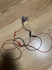
I am not sure if it would work with your solar charge controller or not, but I built a small test system to show another path toward pre-charging the inverter input caps. The basic idea is to use solar to charge up the system before turning on the battery pack. Some solar charge controllers will do this, and some will only turn on if they detect an "in range" battery voltage.

 
Well I had a chance to borrow my mechanics high end torque wrench. Sadly its lowest setting was above 6 nm. Considering the stories of snapped screws on battery cells I elected to use a torque screwdriver that has been recommended by others. It is not digital but has a fairly easy scale for adjustments. I really liked that it came with a 1/4 to socket adapter. This made tightening up the screws on the terminals much easier. I went shy of 6 nm. They are still quite snug and should be fine.
Is there a page that shows the torque specs for the batteries?
 
So I have been careful not to drill into the dolly frame in case it somehow affected the structural integrity. To that end I have opted for these zip ties. Must say I am favorably impressed so far:


IMG_3839.jpeg
 
I believe that the one thing all members strive for in building their systems is to be as safe as possible. Sometimes one walks the path between need to have versus want to have. Then there are things like code and other considerations along the way.

I took a number of steps to try to ensure safety with this build. If I were to build this again in a couple of years I might choose a different path based upon experience and comfort levels with concepts. I wanted to share considerations that appealed to me with this build. This is by no means a recipe as there are multiple routes to arrive at the same conclusion.

Dolly: I liked this because it offered a variety of position options. Because I added a rear wood frame, I am only able to take advantage of two of the three position options. In the upright position it is rated at 800 pounds. At the 45 degree angle it will handle 500 pounds which far exceeds what I have installed. At the 45 degree position movement will also be far easier for me.

Battery wooden holder: This was a custom one of a kind. In putting this together I felt more comfortable applying a high quality wood glue prior to connecting the various pieces. This went through two revisions as I considered and improved on things. The timber lag bolts I applied at the rear of the box are designed for timber walls in outdoor applications so should very adequately handle the stresses.

The two aluminum angle pieces that secure this to the dolly were discussed in agonizing detail earlier. They work quite nicely for holding things together.

Fusing: The battery box has a breaker installed. I am utilizing this as an on off switch and am using a second fuse at the bus bar which actually has a lower rating so it would stops things first should they get out of hand. Perhaps a bit of OCD on my part but if I sleep better at night all the better.

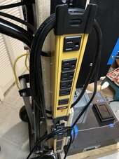
Power distribution: There is a Square D distribution box with two 15 amp breakers. They each feed an outlet bar which has ETL rating and a 15 amp breaker switch. Redundant I know. I found them cool looking and the fact that they had safety features built in was an added plus for me.

Victron components: What can I say. I think they look cool. One of the key considerations for the Multiplus II is that it sips power in idle mode. I shared earlier how the Multiplus allows redundancy with my other build which for me is a plus.

Battery case: This thing is cool and well featured. Thank you again Amy for making this product available. I am looking at updating my other cases with this design in the near future.

AC input: This went through at least two versions. I opted for the junction box approach for personal reasons. I saw at least two benefits, first the wire clamp on the AC input helps prevent pulling a connection loose. Second I was able to get a better wire connection to the Multiplus II.

Future options? I am considering adding stainless steel support wires on each side of the box and attach them to the wooden frame. Too much? Perhaps. But then that is one of the benefits of being your own contractor.

Solar panel input. I already have one mobile panel discussed in another thread. I am considering another mobile design that I hope to build this spring which will be lower to the ground while still having the ability to adjust the angle. I want to have the ability to charge this build from a panel or two in the future which is why I added the charge controller.
 
Last edited:

diy solar

diy solar
Back
Top