diy solar

diy solar

Watts247 8 in/ 2 out Combiner Box: Internal Component Temps Seem Dayum Hot !!

This is a discouraging thread. Wish we could have a DIY combiner box build, and list of materials. I’d do it but I’m nowhere near capable or competent.
 
  • Like
Reactions: JRH
This is a discouraging thread. Wish we could have a DIY combiner box build, and list of materials. I’d do it but I’m nowhere near capable or competent.
Are you referring to a custom build thread? I mean the Midnite Solar units aren't that complex. They're just some purpose built steel box, some DIN rail, Breakers and maybe fuses depending on which model.

I think the issue I was having was in the schottky diodes and the rectifiers on the circuit board (I'm speaking over mystery pay grade), and the cheap Chinese Breakers that are used in those watch247 boxes.
 
I know this is an older thread but I just came across it and thought I would posting as I need to upgrade our combiner box and am hoping for your insight/suggestions.

Thank you for documenting this thread @MrM1 and to @timselectric , @JRH , @Hedges and everyone for your replies. I learned a lot.

A quick explanation. I am new to solar and off-grid. My husband & I decided to go this route as we built a new house on a farm a significant distance from power. The project started during covid when all solar companies were busy so we bought equipment from an off-grid seller and an electrician did the hookup. We have had a few issues come up so I have been trying to learn what I can on my own so I can better understand how it works. I do not have electrical knowledge other than what I have learned online so please bear with my ignorance.

Breakers in the combiner box worked for a while then started tripping more and more, and last week one melted. I want to get it resolved asap to avoid any more overheating issues but also want to make sure the equipment and setup is correct this time.

Equipment I have:
- 16- 450W panels wired in strings of 2 panels each, then paralleled in the combiner box into two separate groups of 8 panels total. So two sets of 2s4p. Each set is connected to a separate MPPT controller (each group of 8 panels connects to a controller).
- Controller specs are maximum 155 Vdc and 100 amps each
- Solar panel specs - 49.3 Voc/V and 11.60 Isc/A each panel
- 48V batteries/system
- Temperatures here can range from -30 C in winter to + 40 C in summer


I understand when you combine 3 or more strings, each string must have its own fuse or circuit breaker and then the combined output will also need a larger circuit breaker (currently our system has each set of panels going into one larger breaker, so 2 larger breakers and that's it). I have seen that fuse size is based on Isc x 1.25 for individual string fusing then *1.25 again for continuous current. In my case 11.60 Isc x 1.25 x 1.25 = 18.125 amps. Rounded up to 20A (which matches the panel "fuse series rating" of 20A specified in the specs).

My questions are:

1. The larger circuit breaker / disconnect for each set of panels would then need to be rated for 80 amps? (20A * 4 series connected). That poses an issue for me because the wire size used by our electrician is #6 which I understand is too small for 80 amps? We can't rewire the panels to have 3 panels per string instead of 2 because that would put the voltage at the maximum our controllers can handle or over in cold temps. So it seems we either have to increase the wire size for 80 amps (difficult to do as they are buried underground for 100 feet from combiner to controllers) or get larger controllers? OR is that not necessary? On the 63A breaker we have now it says trip amps of 81.9. So would the 63A breaker still be sufficient? I also saw someone say that MidNite's circuit breakers that are rated for 100% continuous full load with no damage so does the panel Isc need to be multiplied by 1.25 twice or just once (in which case each big breaker would be 11.60 * 1.25 * 4 series panels = 58 amps (rounded to 60 amp breaker) ?

That would solve the wiring size issue. But I want to make sure the breakers won't keep tripping like they have been. Today the amps on one controller showed 71 amps for a couple seconds (in full sun is was consistently between 60-69 amps). Our breakers were originally 50 amps (trip amp 65), which makes sense now why they were tripping. The electrician replaced them with 63 amp breakers but one melted a few weeks after the switchover (not sure if it was a loose connection or still too small of Amps for the input, or if it's because the combiner box is rated for 120 A max - did not see that until after).

2. If it's an option to keep a smaller breaker like 63A, do we then have to use smaller breakers/fuses for each series? Can we use Midnite's 15A breakers rated for 100% continuous output rather than 20A fuses?

3. Is it better to use fuses or breakers for each string, or does it matter? I feel like if use breakers then if one tripped it would be easier to see where the issue is (rather than opening each fuse box to find the right one) and the breaker can be flipped back on rather than replacing a fuse. But I see more about fuses so just wondering if there is a benefit of using one over the other?

4. I was going to purchase the same combiner box as you did @MrM1 until I saw the issues you were having (and realized we need 20A fuses and they only have 15A). I cannot find any other combiners that do 8 in / 2 out or two 4 in / 1 out other than to use Midnite Solar MNPV12 or use two Midnite 6 combiners. If I do two Midnite 6 combiners, can I put the 4 series fuse/breakers in the box along with the larger circuit breaker?

5. I saw someone said to use non-polarized breakers. I believe the ones we had were polarized. Are either of these correct?
OR this one
(that one offers single pole or double pole - which is best?)

Thank you!
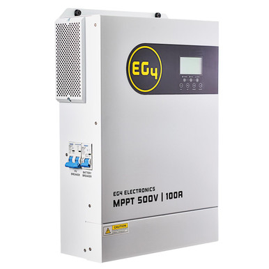
 
The #6 is currently too small.
You have two options.
1. Replace the #6 with #4.
2. Replace the SCC's for a higher voltage ones. And reconfigure the arrays.
 
Tripping and melting probably due to loose connection.

I would use the Midnight magnetic hydraulic breaker. Then the extra 1.25 factor isn't needed.

11.6A Isc x 1.25 x 4 = 56.25A, so 63A breaker, and 6 awg (3 in a conduit) OK to 65A using 65C column.

Keep the 20A fuse per string; those are thermal, needs 1.25 x 1.25
However, magnetic hydraulic breakers 15A would be OK (if non-polarized, or if all ganged to switch together).
With 4x 15A, you would not need the separate 63A.

I guess PV array orientation if fixed? I'd rather have some strings oriented differently, which reduces peak current.
Anyway, Isc only happens on a cool day, when wires and fuses have cooler ambient.

Prefer non-polarize, but for single breaker feeding 6 awg wire, polarized is OK.
Only places non-polarized is needed is each individual string (but you have fuses) and between SCC and battery.
(But I think ganging poles of breakers for all PV strings makes it OK to use polarized.)
 
Thank you very much @timselectric and @Hedges - that info helped a lot.

@Hedges you said I could either use a 20A fuse per string and then connect 4 strings into a 63A breaker (non-polarized) OR use 15A magnetic hydraulic breakers for each string and wouldn't need the 63A breaker. Is there a benefit of using one of of those options over the other? Is one less safe, cause more heating up, or tripping, or any negatives I am not thinking of? Just wondering which is the better way to go.

I agree that re-configuring the arrays would be better to reduce peak current. Am I understanding my charge controller specs correctly in that we can't have 3 panels in a string? When I look at controllers online it seems like most have 150 volt max rating, but if my panels are rated for 49.3 Voc/V x3 = 147.9 V. That is less than the 155 Vdc solar input rating on each controller (specs attached) but I read somewhere that you also have to adjust for ambient temperature. We can get to -20 to -30 celcius in winter which in a chart said to multiple by voltage by 1.20 which is then 177.48 volts which would be over my controller limit. The amount of amps the controller allows is no problem. If that math is correct then I can only have 2 panels in a string unless I find a charge controller that allows 200 volts?

Thanks again!
 

Attachments

  • controller specs.jpg
    controller specs.jpg
    177.8 KB · Views: 3


8s2p should work fine for your panels.
 
As others have said here, you are severely limited by your charge controller and as Tim has perfectly pointed out, that unit from SS would be your best way forward.
 
@Hedges you said I could either use a 20A fuse per string and then connect 4 strings into a 63A breaker (non-polarized)

Single 63A or 60A DC breaker could be either polarized or non-polarized.
Direction of current flow is from PV panels; PV+ from panel is highest voltage, goes to (+) terminal of a polarized breaker. Assuming 2 pole, PV- from panels is lowest voltage, goes to (-) terminal of a polarized breaker.

That would work with 20A fuse or breaker per string. If breakers, they need to be non-polarized, or if polarized they need to have all poles ganged. If that is a pole with sufficient voltage rating for the string, 4 poles ganged would do it. If poles are rated for only half the voltage of string, each string needs to be interrupted by 2 poles connected in series and that would be 8 poles ganged. (fuses easier to get of required voltage. Since strings are 2s of 49Voc panels, single pole can interrupt the current.


OR use 15A magnetic hydraulic breakers for each string and wouldn't need the 63A breaker.

Yes, magnetic-hydraulic don't need the extra 1.25x so 15A would do.

If polarized, all poles of all strings need to be ganged to trip together. Because string voltage is about 100V or so and one pole is enough for the voltage, that's just all poles on PV+ ganged together. Four other poles on PV- would be ganged together, but don't have to be ganged with PV+

(That's not something coming from NEC or other authoritative sources, just my reasoning: If one is tripped with reverse current, it can't interrupt the arc, but it turns off the other three with forward current.)

Is there a benefit of using one of of those options over the other? Is one less safe, cause more heating up, or tripping, or any negatives I am not thinking of? Just wondering which is the better way to go.

Magnetic-hydraulic breakers don't have a heating element, so not much heating.
I think one 2-pole 63A breaker to isolate the string, and one fuse per string, would be simple and convenient.
Fuses are available with 1000V rating. A ganged 2-pole breaker will be 300V or maybe more. This supports higher voltage system if you change inverter/SCC later.

You can use MC4 fuse holders if you like. But may be difficult to find ones with same brand connector as PV panels (don't mix and match.)

If you get 8x 15A breakers, either non-polarized or you gang with handle ties, that is fine too. More a matter of price you see.
This would probably be limited to string with the 150V max unless (1) unpolarized or (2) you gang all 8 poles. There may be a limit of how many can be ganged and trip each other.

If those are 15A 2-pole 300V non-polarized breakers, will also support higher voltage system.
 
Thank you all very much for your suggestions and insight! That helped a lot. Much appreciated.
 
Back
Top