By definition the fuse will protect the wire; what we will never know is if the fuse was just one of many potential ignition sources in this failure at the time the fuse blew... which is why you want to isolate the string sooner than the fuse can do it if there is a failure.My assumption is in that failure condition a class T wouldn't have provided a spark. Now the high current might have still heated the wires enough to melt the sheath and short and still caused a fire.
We will never know.


You are using an out of date browser. It may not display this or other websites correctly.
You should upgrade or use an alternative browser.
You should upgrade or use an alternative browser.
House burned down
- Thread starter Jejochen
- Start date
robbob2112
Doing more research, mosty harmless
So if I had 2 parallel 16s batteries, each with their own bms would this be safe against a cell short?
And if I had a class T fuse on each string that would be an additional backup if the bms failed to protect?
Two batteries means if one has a short the other will dump, but the current isn't enough to cause a fire if both batteries are fuse.
For batteries and only two I would put MRBF on the positive post and call it a day. Maybe a class T to the inverter depending on the current expected. Class T would of course be better at higher current.s
Add more batteries and you need to fuse both ends of the cable to the bus bar unless it is shorter than 7"or so. The a class T to the inverter is mandatory.
With particulars no. Can use the correct circuit breaker in an either or case…..or both.Two batteries means if one has a short the other will dump, but the current isn't enough to cause a fire if both batteries are fuse.
For batteries and only two I would put MRBF on the positive post and call it a day. Maybe a class T to the inverter depending on the current expected. Class T would of course be better at higher current.s
Add more batteries and you need to fuse both ends of the cable to the bus bar unless it is shorter than 7"or so. The a class T to the inverter is mandatory.
What the one person stated is also case if the fuse or breaker does not see substantial amp to blow or trip then it will not prevent failure. Strings in parallel will be passing current…. To damaged cell.
We don’t even know what the source was except fire man inspecting this charred mess saying a fuse. He was offering educated experienced = GUESS.

In aviation never worked on anything that crashed. Often times they tried blame the ppl that worked on it last as first suspect. I never endured it but knew ppl that did.
Glad OP made it out. Think it might never be solved … we are Guessing. While living dangerous. Inherent risk like driving and flying
_voltmeter_
New Member
- Joined
- Apr 24, 2022
- Messages
- 65
there is always a fuse needed. the fuse protect the wiring, the bms the battery.So if I had 2 parallel 16s batteries, each with their own bms would this be safe against a cell short?
And if I had a class T fuse on each string that would be an additional backup if the bms failed to protect?
if you have one bms on each paralel bank, the faulty bank will shut down and not allow dumping current from the working bank.
dont place the bms above the cells without heat shielding, else it will burn with the faulty cell and cause a catastrophic failure
robbob2112
Doing more research, mosty harmless
With particulars no. Can use the correct circuit breaker in an either or case…..or both.
What the one person stated is also case if the fuse or breaker does not see substantial amp to blow or trip then it will not prevent failure. Strings in parallel will be passing current…. To damaged cell.
We don’t even know what the source was except fire man inspecting this charred mess saying a fuse. He was offering educated experienced = GUESS.
View attachment 214740
In aviation never worked on anything that crashed. Often times they tried blame the ppl that worked on it last as first suspect. I never endured it but knew ppl that did.
Glad OP made it out. Think it might never be solved … we are Guessing. While living dangerous. Inherent risk like driving and flying
We had one of our aircraft have a hard landing - this was in Guam - when it hit, the rivits holding the depleted uranium slug broke and it made its way through the bottom of the airplane next to the tail and skidded all the way down the runway and off into the jungle. The airplane was not otherwise damaged fortunatly.
But it did qualify and a class A mishap because of the cost to get a team out and re-attach the slug in the right spot. We had to go and do search party to find the slug by following the trail it left then stay 10ft away until the guys in radiation suites came to retrieve it. The thing weight a bunch for such a small thing but I suppose it was also encased in a lead jacket.
They decided to send it through weight and balance in Japan after a one time CNO authorized flight. The slug was installed to balance out the gear forward of the center of balance.
But I get what you are saying and we have all said I think - we will never know what the actual cause was.
"safe" is a little ambiguous, as is "bms". A mosfet-based BMS should be able to handle the current for one donor string, but if the charger is also contributing then you might be at the point where the mosfet would fail open. Most people will size a fuse at 125-150% of the BMS rating (adequate to protect the wiring), which might not be low enough to handle the decaying balance current.So if I had 2 parallel 16s batteries, each with their own bms would this be safe against a cell short?
And if I had a class T fuse on each string that would be an additional backup if the bms failed to protect?
BUT, a cell should not just vent catastrophically based on charging at 7% over normal. Likewise, most cell shorts under normal operation should be high impedance. A dead short of a single cell is a problem in its own right, as is damage to the cell casing.
But for "normal" levels of safe if you fuse your strings at the 1C rate (never exceed 0.8C) with a fuse that has sufficient interrupting rating then you have a fairly reliable solution even if your BMS fails to isolate the string. (You might use up a lot of fuses though.)
_voltmeter_
New Member
- Joined
- Apr 24, 2022
- Messages
- 65
50/50 chance if a fuse can save the paralel bank, it is the job of the bms. the bms save the paralel bank with a chance of 99%with a fuse that has sufficient interrupting rating then you have a fairly reliable solution even if your BMS fails to isolate the string.
so mr murphy would go for that 1% and the 50% of no chance for the fuse to trip
it is nothing wrong to use class t fuses but rely only on them to protect the battery is not a good solution.
robbob2112
Doing more research, mosty harmless
"safe" is a little ambiguous, as is "bms". A mosfet-based BMS should be able to handle the current for one donor string, but if the charger is also contributing then you might be at the point where the mosfet would fail open. Most people will size a fuse at 125-150% of the BMS rating (adequate to protect the wiring), which might not be low enough to handle the decaying balance current.
BUT, a cell should not just vent catastrophically based on charging at 7% over normal. Likewise, most cell shorts under normal operation should be high impedance. A dead short of a single cell is a problem in its own right, as is damage to the cell casing.
But for "normal" levels of safe if you fuse your strings at the 1C rate (never exceed 0.8C) with a fuse that has sufficient interrupting rating then you have a fairly reliable solution even if your BMS fails to isolate the string. (You might use up a lot of fuses though.)
So, earlier it was talked about - if a DIY battery gets a case short between two cells that makes one of those a dead short across the terminals. From that is born chaos. And all it takes is a metal shelf, a hole in the plastic wrap, or some otuer damage causing that short. Separators prevent most of that if done right.


robbob2112
Doing more research, mosty harmless
Possible solution:
View attachment 214820
BACK UP.
View attachment 214821
This guy is FUSED1 on each battery, 1 300amp anl and 1 T class.
Link for the contactor?
The MRBF is probably OK, but I get them from Mouser for eaton brand.
ScrotpusGobbleBottom
Corn Pop was a bad dude.
Do you think this is excessive?This guy is FUSED
Link for the contactor?
The MRBF is probably OK, but I get them from Mouser for eaton brand.
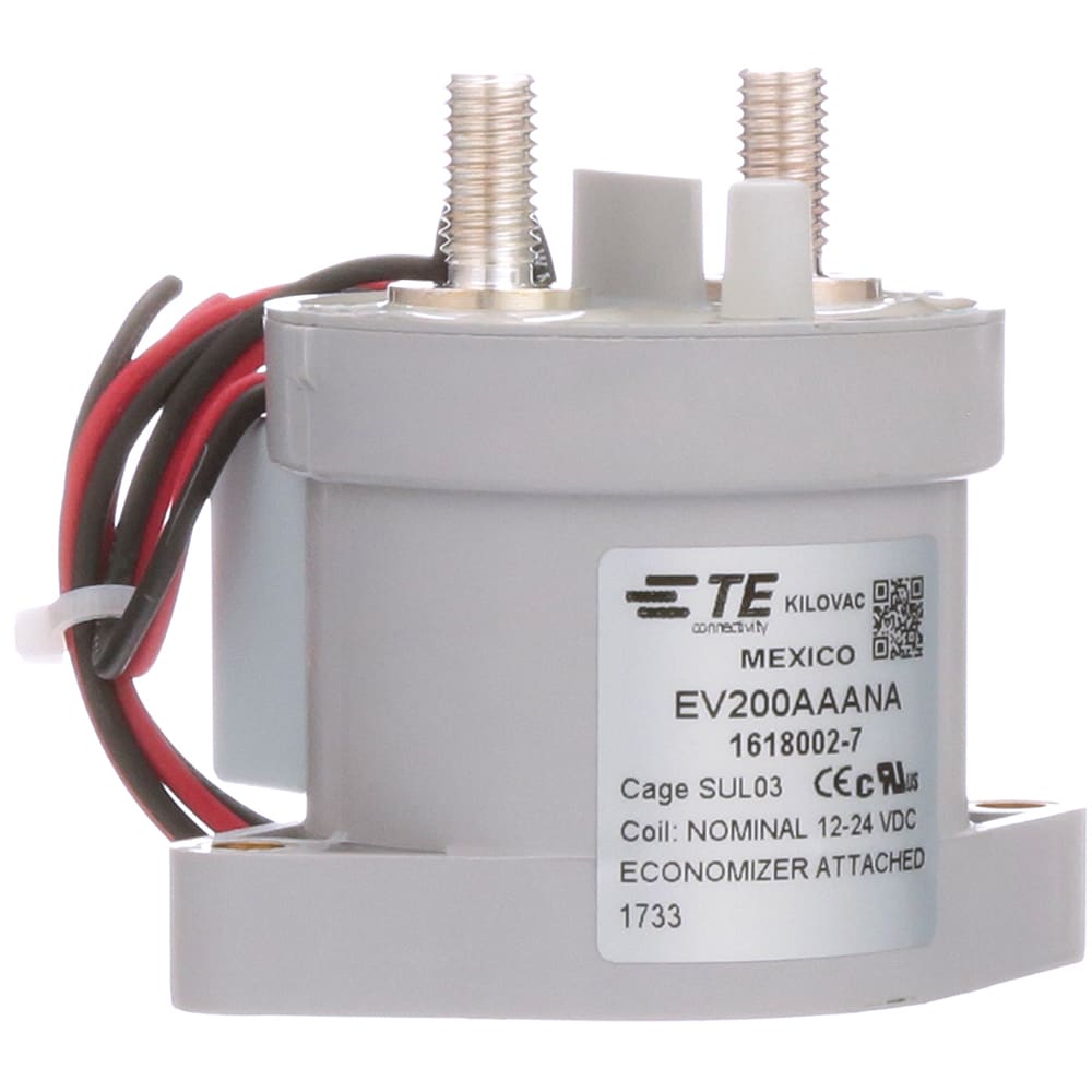
TE Connectivity EV200AAANA 500a 0-900vdc Tyco 12/24v
These were recovered from EV battery modules. These are VERY EXPENSIVE online. If you have any project that needs a high current relay this is your chance to save some money. Make a cheap 30a BMS into a 500a BMS. This will work for batteries in the 9-36v range so perfect for Lifepo4 and Lithium...
 batteryhookup.com
Do you think this is excessive?
Kind of over board but I tend to build things with a fuse and breakers with fuse slightly higher amp rating than breaker to protect. Got them on inverter and 4 bms The breaker can be reset after fault is cleared. The fuse is back up to breaker.
He made a whole lot of extra connections that can get loose and cause problems.
I mrbf per battery , 2 system anl 300amp, and a t class. I’d chuck the 300amp anl fuses.
He has 1 inverter T class fuse and 6 battery mrfb fuses. Plus 6 bms. He shakes worse then I do - he could be a natural welder. I’d lay money he had a fire.

Friends with trolling motors use them on batteries … they work…..according to friends. The inverter fuse is a must. The battery fuses are parallel.
He could easily run a battery hook up type contactor on each of his bank strings and do away with the cut out switches and 300amp anl fuses. Be my advice. Less connections. I think he is running 12vdc inverter system …. His cables look thin to me.
robbob2112
Doing more research, mosty harmless
These arrived today. I won't be able to fiddle until tomorrow until then. But, they are hefty and a very heavy duty built.
The casing on the fuses are ceramic and the end caps are nickle plated. The holders are also heavy duty built. When it is inserted it takes a flat screwdriver to remove them from the holder. There are tabs on the front which probably match up to an extractor which I will hunt for if I use them.
The AIC is considerably higher than for class T but I didn't look for time vs current curves yet. But unless they are crazy I think this might be a very low cost alternative to class T.
When I test I'll hook up meters and check resistance as they heat up then see is they blow close to the rating. It looks promising though.
And when I blow them I'll cut them open to see what is inside and how they were constructed.
Will make a video of the actual test when it blows so I can review and get the time things.
Will post that to youtube so it is accessible, I don't have a channel or want one so not sure how to do that anonymously. Any pointers?
This is the link
This is the removal handle
Last edited:
ScrotpusGobbleBottom
Corn Pop was a bad dude.
For sure.I’d chuck the 300amp anl fuses.
AgreedHe made a whole lot of extra connections that can get loose and cause problems.
42OhmsPA
What's in a title?
I'd use a different service but I don't have any to suggest.Will post that to youtube so it is accessible, I don't have a channel or want one so not sure how to do that anonymously. Any pointers?
Thank you for taking the time to test something different for the community.
robbob2112
Doing more research, mosty harmless
TE Connectivity EV200AAANA 500a 0-900vdc Tyco 12/24v
These were recovered from EV battery modules. These are VERY EXPENSIVE online. If you have any project that needs a high current relay this is your chance to save some money. Make a cheap 30a BMS into a 500a BMS. This will work for batteries in the 9-36v range so perfect for Lifepo4 and Lithium...
Kind of over board but I tend to build things with a fuse and breakers with fuse slightly higher amp rating than breaker to protect. Got them on inverter and 4 bms The breaker can be reset after fault is cleared. The fuse is back up to breaker.
He made a whole lot of extra connections that can get loose and cause problems.
I mrbf per battery , 2 system anl 300amp, and a t class. I’d chuck the 300amp anl fuses.
He has 1 inverter T class fuse and 6 battery mrfb fuses. Plus 6 bms. He shakes worse then I do - he could be a natural welder. I’d lay money he had a fire.
Friends with trolling motors use them on batteries … they work…..according to friends. The inverter fuse is a must. The battery fuses are parallel.
He could easily run a battery hook up type contactor on each of his bank strings and do away with the cut out switches and 300amp anl fuses. Be my advice. Less connections. I think he is running 12vdc inverter system …. His cables look thin to me.
Ordered 2 of them to play with. More fun in the sun.
Does anyone have recommendations on Class T fuses and holders to use? I have two 48V 5kW batteries right now, but will eventually expand to six (30kW total).
I'm assuming I want 300A Class T fuses? I'm using the mega fuses right now from victron which don't seem to be a good idea from what I've gathered in the thread so far.
I'm assuming I want 300A Class T fuses? I'm using the mega fuses right now from victron which don't seem to be a good idea from what I've gathered in the thread so far.
SilverbackMP
Solar Addict
- Joined
- Apr 4, 2022
- Messages
- 1,008
Blue Sea are usually what’s recommended and what boaters (who have even a greater fear of fire) usually use. Not sure on your amperage needs. I used 300A breakers (along with 250 A MidNite breakers), with amp ratings base off a bit of discussion here but mostly base on the folks that sold me my BMS units. But that was figured for 8x 230A 48v batteries (will be adding four more) with a max continuous draw of 24 kw. I suspect the size of the fuse would be dependent on inverter capability and number of batteries. But I am not 100% sure on this and someone that’s much smarter than me should and will chime in (not sure why I am even giving my two cents lol).Does anyone have recommendations on Class T fuses and holders to use? I have two 48V 5kW batteries right now, but will eventually expand to six (30kW total).
I'm assuming I want 300A Class T fuses? I'm using the mega fuses right now from victron which don't seem to be a good idea from what I've gathered in the thread so far.
ArthurEld
Solar Wizard
People used to recommend that each battery should be set up to handle the max your system can charge/discharge. My Solark max charge discharge is 185 amps so I used 200 amp class T fuses for each battery.
But now I am reading some people recommend using smaller class T fuses for systems with multiple parallel batteries. My system has 5 batteries so each battery might see 50 or 75 amps max when they are all up. I'm wondering if it would be safer to use smaller fuses like 100 amps or even smaller since it would be very unlikely that each battery would ever see more than 100 amps even if a couple batteries went offline.
Are there new recommended class T fuse sizes for multiple battery systems? I would really like to find more info about this idea.
_voltmeter_
New Member
- Joined
- Apr 24, 2022
- Messages
- 65
fuses are not for battery protection, they are for protecting the wiring
use a bms on each paralel bank and a fuse with rated voltage above 60v (16s) for the wiring
mega or t class fuses can be used
use a bms on each paralel bank and a fuse with rated voltage above 60v (16s) for the wiring
mega or t class fuses can be used
squowse
Solar Enthusiast
- Joined
- Jan 4, 2021
- Messages
- 605
I was thinking if the current burnt out the BMS components and caused an arc within the BMS. Then the fuse would blow shortly after.50/50 chance if a fuse can save the paralel bank, it is the job of the bms. the bms save the paralel bank with a chance of 99%
so mr murphy would go for that 1% and the 50% of no chance for the fuse to trip
it is nothing wrong to use class t fuses but rely only on them to protect the battery is not a good solution.
I was thinking if the current burnt out the BMS components
There is no current through the Batrium BMS. It uses a contactor, current isn't going through the BMS like in a MOSFET based BMS.
robbob2112
Doing more research, mosty harmless
These arrived today. I won't be able to fiddle until tomorrow until then. But, they are hefty and a very heavy duty built.
The casing on the fuses are ceramic and the end caps are nickle plated. The holders are also heavy duty built. When it is inserted it takes a flat screwdriver to remove them from the holder. There are tabs on the front which probably match up to an extractor which I will hunt for if I use them.
The AIC is considerably higher than for class T but I didn't look for time vs current curves yet. But unless they are crazy I think this might be a very low cost alternative to class T.
When I test I'll hook up meters and check resistance as they heat up then see is they blow close to the rating. It looks promising though.
And when I blow them I'll cut them open to see what is inside and how they were constructed.
Will make a video of the actual test when it blows so I can review and get the time things.
Will post that to youtube so it is accessible, I don't have a channel or want one so not sure how to do that anonymously. Any pointers?
This is the link
This is the removal handle
Fiddle time limited - only time for pictures and a couple of measurements with the 1035


Turns out I do have a Mega fuse.
The Chints are HUGE compared to the Class T fuses but they have much higher AIC.
This is the link
This is the removal handle
Resistances in order
200a Chint - 0.35 mohm
300a Class T - 0.22 mohm
200a Class T - 0.88 mohm
125a Chint - 0.20 mohm
100a Mega - 0.50 mohm
200a Breaker - 1.48 mohm - brand is "Red Wolf" off amazon
All measurements taken with 4 wire leads on the ends of the actual fuse. I did measure some of the resistance on the mounts end to end with the fuse but didn't record the reading.
My plan is to run as many amps as I can put through them with a clamp meter to monitor and the 1035+ meter to measure the resistance and how it changes over time.
And if I can find a 3rd set of hands I'll also use the trusty Fluke to measure voltage drop across the fuses.
The 1035 is a mico-ohm meter that measures resistance with a 1kh sine wave verse the standard straight DC current measured by a voltage divider network.
I won't blow the Class T fuses, they are just to spendy, but I will blow the anl, mega, and chints to see how they work out.
I'll use a ceramic heater with fan and a heat gun as loads to blowthe fuses. I have a 2000w inverter and a 1200va victron and will probably have to put both on a bus bar to make it work. I do also have the victron smart shunt to measure the current as well and it should retain the graph as I turn things on.
Will draw up a diagram of what I am doing and post.
Also, I think after this post I will either put the results in a Resource or a separate post by itself.
Last edited:
How about source web links to those fuses and fuse mounts?Fiddle time limited - only time for pictures and a couple of measurements with the 1035
View attachment 214918
View attachment 214919
Turns out I do have a Mega fuse.
The Chints are HUGE compared to the Class T fuses but they have much higher AIC.
Resistances in order
200a Chint - 0.35 mohm
300a Class T - 0.22 mohm
200a Class T - 0.88 mohm
125a Chint - 0.20 mohm
100a Mega - 0.50 mohm
200a Breaker - 1.48 mohm - brand is "Red Wolf" off amazon
All measurements taken with 4 wire leads on the ends of the actual fuse. I did measure some of the resistance on the mounts end to end with the fuse but didn't record the reading.
My plan is to run as many amps as I can put through them with a clamp meter to monitor and the 1035+ meter to measure the resistance and how it changes over time.
And if I can find a 3rd set of hands I'll also use the trusty Fluke to measure voltage drop across the fuses.
The 1035 is a mico-ohm meter that measures resistance with a 1kh sine wave verse the standard straight DC current measured by a voltage divider network.
I won't blow the Class T fuses, they are just to spendy, but I will blow the anl, mega, and chints to see how they work out.
I'll use a ceramic heater with fan and a heat gun as loads to blowthe fuses. I have a 2000w inverter and a 1200va victron and will probably have to put both on a bus bar to make it work. I do also have the victron smart shunt to measure the current as well and it should retain the graph as I turn things on.
Will draw up a diagram of what I am doing and post.
Also, I think after this post I will either put the results in a Resource or a separate post by itself.
Watch this
~3:30 mark watch Will Prowse test a T class fuse.
Similar threads
- Replies
- 3
- Views
- 195
- Replies
- 174
- Views
- 7K
- Replies
- 90
- Views
- 10K