diy solar

diy solar

Ground rod specifics

It is more for lightning and radio frequencies. Think of a large energy entering the ground rod at the ground level and traveling in all directions at the speed of light creating a half sphere. Having two rods the two fields will overlap and be out of phase with each other due to the wire length feeding the ground rod.
View attachment 220839
I understand the need for distance when placing rods what I'm saying is there should never be an exception to your resistance.
once you meet your desired resistance rating you can then test for loop impedance to work out how big your cable size needs to be, at least that's how I was taught.
 
Is it helpful to water the ground rod(s)?

It would be a simple matter to have the air conditioner condensate line in the area.
 
Is it helpful to water the ground rod(s)?
Yes you will obviously get better conductivity compared to dry earth the resistance on our house will increase a fair bit during the end of summer until the rains come in spring.
It would be a simple matter to have the air conditioner condensate line in the area.
That's not a bad idea tbf why did I never think of it
 
So the exception is dangerous I've had to fit 5 rods on my home here to get an acceptable reading of 5ohms and I likely need more as this was not mesured during a dry spell
No
The exception says that if you install 2 x 6' apart, resistance reading isn't required.
The connection to earth is only as good as the conductivity of the local earth.
Two is plenty, no matter how conducive the local soil is.
If the local soil is very conducive, then the earth connection is very important.
If it's not, then the connection is less important.
I just drive the two required, and it takes care of itself.
 
Each to their own I guess.
UK and Europe demand a resistance of 5ohms or less and rods need to be placed the same distance apart as their depth.
 
Definitely
No matter what. If you want to pass an inspection, you must follow the local regulations.
 
You can also get a one shot cadweld to weld the wire to the ground rods to prevent future corrosion resistances. Living in Florida working on towers we take grounding seriously. Lightning capital of N America.
 
I'd be more inclined to go overboard and try prevent death than just meet local regulations, especially here where I live.
 
The regs this post is quoting kinda laughable to me as an retired British electrician we simply had to drive as many rods as was necessary to get a good ohms reading

So the exception is dangerous I've had to fit 5 rods on my home here to get an acceptable reading of 5ohms and I likely need more as this was not mesured during a dry spell

Wish they had these when I was an apprentice saw one on YouTube a few years ago ended up making my own but for my little SDS plus
I tried using a plus for it, it took FOREVER! Gotta have a max to pound through red clay!
 
Each to their own I guess.
UK and Europe demand a resistance of 5ohms or less and rods need to be placed the same distance apart as their depth.

This used to be in the motorola spec for transmitting towers. Now they just do the ground when they prepare the site.
 
NEC wants 25 ohms or less to ground OR 2 rods. Seems they waive the requirement to even measure it if you have 2 rods.

5 ohms seems quite strict when measuring dirt?
Thinking it's more to do with lightning and how well the GFCI works as well as other sensitive equipment, average human resistance for a cardiac event is 400 ohm at 220V so as long as we have a ground well below that it's all good.
 
Thinking it's more to do with lightning and how well the GFCI works as well as other sensitive equipment, average human resistance for a cardiac event is 400 ohm at 220V so as long as we have a ground well below that it's all good.
Nothing to do with lighting. This is electrical safety. Lighting protection is a completely different system.
And you are miss interpreting the purpose of the ground rod.
The ground rod provides a return path to the N/G bond, in case the earth becomes electrified.
Generated electricity can only flow in a completed circuit. (From the source, and back to the source)
We ground/bond everything that is conductive and can be touched. So that in the event it becomes electrified, there is a low impedance (resistance) fault current path back to the source. Which completes the circuit and allows the protection device to open the circuit and make it safe.
Before someone touches it and becomes part of the circuit.
Ahh right I guess this is where your confused type-b GFCI devices weren't a mandate in the UK until recently and still only on new installations so as far as DC the ground is your primary protection not the GFCI. More Worrying is that unless it's a new install many people in the UK still don't have any form of earth loop safety device so the earth is their primary protection for AC also.

But it does pose an interesting question, how many of the DIY community on here have type b GFCI devices on the DC side of their installs?
The grounding system is not the protection.
It just provides the fault current path (back to the source), so that a protection device can function quickly.
GFCI's (and RCD's) work by measuring current flow and detecting when it's flowing somewhere it shouldn't.
Current can only flow, if it has a return path to the source. Whether that path is the designed path, or an alternate (fault) path.
Please read my statement when the GFCI doesn't trip with DC current (type A which is only a recent change to British regulations that specifies type B) or there is no GFCI,RCD,RCBO or ELB the earth is the primary protection hence why they are so focused on earth being below 5ohms.

British regs are also only a requirement for new installations and if an electrician works on a system that doesn't have any protection they used to only (by law) make a notification and we're not required to install one. I used to work at alot of stately homes back before I retired and I'd say 5% actually had any kind of earth loop protection. Hell Lady Rolls (Rolls-Royce) had sockets from the 1930s in her house 3 prong like current UK plugs but the pins were round and that was still technically legal and within regs.

Also what if your earthing device fails? Regs are literally for liability and insurance purposes, personally I'd want to over engineer any system especially for myself and put redundancy on redundancy to keep myself and my family safe.
 
Please read my statement when the GFCI doesn't trip with DC current (type A which is only a recent change to British regulations that specifies type B) or there is no GFCI,RCD,RCBO or ELB the earth is the primary protection hence why they are so focused on earth being below 5ohms.
The earth provides no protection, on its own.
If it's not part of the return path (bonded), it just becomes electrified in a fault condition. (Same as anything else conductive)
 
Not arguing with you Tim but curious about whether the grounding system provided any protection.

If I have something with an electrical charge, like a big array up on a wood frame, and I touch it, the charge between the array and ground will pass through me, right? But grounded, the array and the ground would be the same. And therefore no shock. Right?

This would be the case for both static charge and a charge generated by the panels that found it’s way to the panel frame.
 
NEC wants 25 ohms or less to ground OR 2 rods. Seems they waive the requirement to even measure it if you have 2 rods.

5 ohms seems quite strict when measuring dirt?
I put in some communications gear in the "sandhills" of NC that spec'd Three(3) Ohms or less. Not possible in that soil. We got it down to 7 if memory serves. I think we had 8 ground rods. They were talking a "ground mesh" or something when the manufacturer rep and engineers backed off. I've never tested here, but I'd bet my two ground rods are drastically lower in this dirt.
 
Not arguing with you Tim but curious about whether the grounding system provided any protection.

If I have something with an electrical charge, like a big array up on a wood frame, and I touch it, the charge between the array and ground will pass through me, right? But grounded, the array and the ground would be the same. And therefore no shock. Right?

This would be the case for both static charge and a charge generated by the panels that found it’s way to the panel frame.
Watch the Holt videos. It's about pathing of the potential This is why you have only one tie point to your ground array. If there is a path electricity will follow it, thus you don't want more than one path to earth. In this case we are trying to protect from an intentionally generated potential creating a fault/path potential where it should not be. The ground in this case is used to detect the fault and trip a breaker. Not static suppression (aka lightning).
 
I put in some communications gear in the "sandhills" of NC that spec'd Three(3) Ohms or less. Not possible in that soil. We got it down to 7 if memory serves. I think we had 8 ground rods. They were talking a "ground mesh" or something when the manufacturer rep and engineers backed off. I've never tested here, but I'd bet my two ground rods are drastically lower in this dirt.
Im curious to how its measured. Does the inspector have his own ground rod he pokes in the dirt 10 inches and tells you how your 8ft ground rod isnt enough???
Seems like they would need 2 of their own rods already in the ground to measure against with acceptable resistance between the two.
 
Im curious to how its measured. Does the inspector have his own ground rod he pokes in the dirt 10 inches and tells you how your 8ft ground rod isnt enough???
Seems like they would need 2 of their own rods already in the ground to measure against with acceptable resistance between the two.
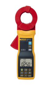
Contrary to what ksmithaz1 said earlier large industrial earthing like this will likely have multiple paths to earth and they use stakeless testing where you test one rod at a time by inducing a voltage then recording the current flow. Single path as you said you drive in stakes and measure
 
I have seen tower crews use this device. I don't know how code enforcement personnel do it.

Fluke 1630-2 FC Earth Ground Clamp​

1718045514607.png
 
Not arguing with you Tim but curious about whether the grounding system provided any protection.

If I have something with an electrical charge, like a big array up on a wood frame, and I touch it, the charge between the array and ground will pass through me, right? But grounded, the array and the ground would be the same. And therefore no shock. Right?

This would be the case for both static charge and a charge generated by the panels that found it’s way to the panel frame.
For someone to get shocked from generated electricity, they must complete a circuit.
Atmospheric charge (static) is always seeking something to balance with.

The grounding system provides a path for fault current back to the source.
So that a protection device will open the circuit and make it safe.
The protection comes from the protection devices.
 
Contrary to what ksmithaz1 said earlier large industrial earthing like this will likely have multiple paths to earth and they use stakeless testing where you test one rod at a time by inducing a voltage then recording the current flow. Single path as you said you drive in stakes and measure
I'm not sure what you are saying. You can run as many ground rods as you want, you should tie them to a single point somewhere above the earth. Everything above the earth needs to tie to that point. We were dinking around in a modest single story L shaped office building. Power company guys laughed out loud when we said we needed 3 ohms to ground.
 

diy solar

diy solar
Back
Top