diy solar

diy solar

Surge protection for PV panels and proper grounding.

Luk88

Solar Enthusiast
Joined
Apr 5, 2024
Messages
315
Location
Poland
This question probably got answered few times on this forum, but I can't find the answers. So forgive me for asking what may be basic knowledge to others.

My current "old" PV system uses no SPD at the array. There is 25m of underground wire, then there is a connection box (on an outside wall of a building, right next to my on-grid inverter) and I have PV DC rated surge protection there and DC breakers. SPDs are grounded to my "main" ground. The main ground is the house and the external building with the inverter. Both grounds are tied together (bonded only in the main panel).

I've watched some videos by Mike Holt and I'm convinced single point grounding is best. So I may even disconnect the extra ground electrode at the second building.

But now the question of surge protection for my new panels comes. These are silicon panels (my old ones are thin film). I believe they are a lot more susceptible to surge damage. So I decided to put some type 2 SPDs at the array. I also run an extra wire to provide the "main" ground.

But then I started having doubts about the idea of placing SPD tied to remote ground while the mount and panel frames are all connected to local ground (all metal mount in concrete).

Imagine a nearby lightning strike, let's say 50m away. This will create a voltage gradient through the earth and the local ground of the panels will suddenly be thousands of volts higher than the system ground. This very high voltage will now "probe" panel insulation which is rated at 1500V only and one or more panels will experience breakdown. This high voltage will flow onto the DC+ or DC and then SPDs will do their job protecting the rest of the system.


Now imagine a second scenario. This time SPD ground is tied to local array ground. Same lighting strike. Local ground goes to many thousands of volts. The SPD activates(it works bidirectionally) and raises DC+ and DC-. Panels are protected because their ground to DC potential doesn't exceed the rating by much... But wait... We now have DC+ and DC- at many thousands of volts as referenced by the main system ground. If there is another set of SPDs right at the AIOs PV input tied to system ground a fight of two sets if SPDs ensues. If the gradient between two grounds is too high both sides get damaged.

So in that case one may say, fine, let's tie the array ground (the mount) to system ground too, so the SPDs do not fight eachother. But that essentially forms an auxiliary electrode with all it's disadvantages (as per Mike Holt). One of them being huge currents flowing on the wire connecting these grounds in case of a nearby strike and if the wire is long it may not even help much because of the impedance of that connecting wire.

So what to do? Not do any SPDs at the array as I did with my old one and hope for luck?

Install SPDs tied to system ground at array? (this seems bonkers, it only protects the inverter, why put it at the array?).

Or connect both grounds together?
 
SPDs are like STP, do they really do anything. Many activate at an extremely high voltage that would still damage equipment. These are primarily to protect the house from fire.

I would add some inductance to make a SPD more effective.

I would keep the ground at external location for best protection. Even Mike holt violates his own rules sometimes.
 
There is 25m of underground wire
Do you run a "main" ground wire out to the PV currently? It sounds like you do not.
...there is a connection box (on an outside wall of a building, right next to my on-grid inverter) and I have PV DC rated surge protection there and DC breakers. SPDs are grounded to my "main" ground. The main ground is the house and the external building with the inverter. Both grounds are tied together (bonded only in the main panel).
This is good, you are protecting the building and inverters where the PV enters the house.
I do the same.

FWIW, I put DC SPDs at the arrays and at the entrance to the house, and tie all grounds together with a cable.
Although I do not explicitly have a ground rod at the arrays, they are effectively grounded there due to the use of metal poles.
Arrays are 220 ft (67m) from the house.

Is there a risk that lightning travels down that cable and the PV cables?
Yes, but it's better than having an ungrounded system.
 
Last edited:
SPDs are like STP, do they really do anything. Many activate at an extremely high voltage that would still damage equipment. These are primarily to protect the house from fire.
Depends on the class/type. Class 1 - agreed 100% these are to protect wiring insulation from breakdown. Class 2.. Mhmm they will protect induction motor windings, some robust electronic devices etc. Class 3 - these do protect electronic devices assuming the devices can withstand 2x the normal voltage for a long time and 3x momentarily.

Are there plenty of devices that die when you exceed their voltage by 20%? Probably, but saying SPDs protect mainly from fire is incorrect.

I would add some inductance to make a SPD more effective.
I'm not sure how that would help, or where to put it. In general the goal when talking about dissipating surges is to lower inductance as much as possible to prevent high impedance to dissipate the surge current.

I suspect you mean an opposite. Increase impedance to present a sort of barrier to surge current, but how do you know the sign of overvoltage, or which conductor it will come from? In such case lowering inductance of everything is the safest IMO.
I would keep the ground at external location for best protection. Even Mike holt violates his own rules sometimes.
So scenario 3. The war of SPDs... 🙄

However I now had another idea, or a realisation. Mike Holt and others alike always talk about connecting it one place. I though what they mean is bonding it to neutral which is done at one place(the main panel) . But perhaps what they mean too is connecting the grounding electrode (including auxiliary electrodes) with system ground in only one place.

So to achieve this I'd need two grounding wires at my array. One is system ground that I connect SPDs to. The other is the conductor that ties the ground mount to the main system ground.

This has an adventage of offering some protection to everything. Still local ground can go very high and system ground will reflect some middle ground(no pun intended). This is less than ideal, but doesn't leave anything unprotected.

I'm not sure. What do people that live in places with lots if lightning do?
 
@ricardocello you replied as I was writing so I reply in a separate post.

Do you run a "main" ground wire out to the PV currently? It sounds like you do not.
No, the "old" array has no ground wire. It has been installed for 3 years with no problems, but it is low ground mount (panels up to chest high) and these are thin film panels. Potentially less susceptible to surges.

This is good, you are protecting the building and inverters where the PV enters the house.
I do the same.
Thanks.

FWIW, I put DC SPDs at the arrays and at the entrance to the house, and tie all grounds together with a cable.
Although I do not explicitly have a ground rod at the arrays, they are effectively grounded there due to the use of metal poles.
Arrays are 220 ft (67m) from the house.

Is there a risk that lightning travels down that cable and the PV cables?
Yes, but it's better than having an ungrounded system.
Do you live in an area where you get lots of lightning?
 
I would add some inductance to make a SPD more effective.
I caution against adding inductance. Inductors tend to create voltage spikes when the current changes. If a surge comes down the line, the inductor current will be spun up, and when the surge ends, that will result in elevated voltages, perhaps even severely negative.

Mike C.
 
I caution against adding inductance. Inductors tend to create voltage spikes when the current changes. If a surge comes down the line, the inductor current will be spun up, and when the surge ends, that will result in elevated voltages, perhaps even severely negative.

Mike C.
That's a cute story. I like that everyone here knows more than I do. It takes the pressure off.
 
@ricardocello you replied as I was writing so I reply in a separate post.
...
Do you live in an area where you get lots of lightning?
Arrays are at the top of hill, and are vulnerable.
⚡I am definitely concerned, but there is only so much you can do about lightning.⚡

Maybe 2-3 good lighting strikes nearby every summer. Have never had a direct strike on property.
There are 500 kV transmission towers nearby, they likely help to attract lightning away from here.
 
Bought those a few weeks ago but haven't installed them yet. On my todo list.
I've been contemplating a pair of midnite 600V two pole breakers instead of the fuses to give me a disconnect function without an additional imo type disconnect.
 
I like a midnite spd600 for each string.
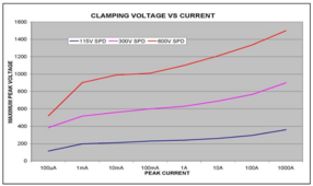
That is what I was planning to do for my three strings but I am concerned they do not conduct heavily enough. The current versus applied voltage curve for MS DC SPD devices:

1717949284644.png

The MNSPD600 doesn't really start to conduct until 1000 volts, and it takes 1200+ volts to get solid clamping of a large surge. For an inverter with a 500 volt max MPPT rating, that seems like not enough and I could easily see damage occurring. This would mean your investment in SPD was really no useful.

My strings max Voc (temperature corrected) will be 401 volts. This makes me wonder if the MNSPD300 device would be better. The spec sheet says the 1 mA current occurs at 423-517 volts for the 300 volt device, so that seems like it would work and it would clamp much harder than the 600 volt device. 1 mA at 401 volts is 401 mW which is something the device could handle indefinitely, and the curve above implies it will be less than 1 mA. This would be using it outside the "nominal" voltage range in the spec, which seems risky somehow.

Mike C.
 
That is what I was planning to do for my three strings but I am concerned they do not conduct heavily enough. The current versus applied voltage curve for MS DC SPD devices:

View attachment 220841

The MNSPD600 doesn't really start to conduct until 1000 volts, and it takes 1200+ volts to get solid clamping of a large surge. For an inverter with a 500 volt max MPPT rating, that seems like not enough and I could easily see damage occurring. This would mean your investment in SPD was really no useful.

My strings max Voc (temperature corrected) will be 401 volts. This makes me wonder if the MNSPD300 device would be better. The spec sheet says the 1 mA current occurs at 423-517 volts for the 300 volt device, so that seems like it would work and it would clamp much harder than the 600 volt device. 1 mA at 401 volts is 401 mW which is something the device could handle indefinitely, and the curve above implies it will be less than 1 mA. This would be using it outside the "nominal" voltage range in the spec, which seems risky somehow.

Mike C.
Yes I had the same thought as I have a 450/100 and max usable voltage is 432V. But decided to go with the 600V as I was worried I'd be running into the protection range. my hope is if there is a nearby strike the SPDs will react quickly enough to clamp down before the magic smoke is released. Technically the batteries and the pv panels are isolated on the rs450 but wanted to protect further down the chain as well if possible.
 
I like a midnite spd600 for each string.

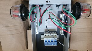
View attachment 220829
But what ground do you use for them on a ground mounted pv array? To system ground? To the array own ground? Do you connect both? And if you do, do you run separate conductor that connects your grounding rods?

I don't know much about that brand other than many people recommend it, but even a best SPD will not save a system if it is not properly applied (not claiming yours isn't, I'm just having doubts about what's the best grounding option for my system).

I've spent a good part of today searching for more info on the subject. It is not even that PV specific. Groups of separate buildings with one shared uility connection and feeders between buildings have the same problem.
Arrays are at the top of hill, and are vulnerable.
⚡I am definitely concerned, but there is only so much you can do about lightning.⚡

Maybe 2-3 good lighting strikes nearby every summer. Have never had a direct strike on property.
There are 500 kV transmission towers nearby, they likely help to attract lightning away from here.

Thanks. That puts things in perspective. I'm o top of the hill too. I too have nearby transmission line (100m) that attracts a lot of lightning.

I couldn't quantify the number. It seems some years it is no problem at all. Some years it is every week during summer.

I've been thinking how utilities do grounding around here on large sites with many buildings. They run a strip of galvanised steel under their ground wire and they connect all the grounding electrodes to that. Unfortunately that way too labour intensive for my site.

This dilemma of whether to connect the (locally grounded) ground mount to system ground is only relevant if panels are susceptible to damage if high voltage suddenly shows up on their frames/surface. Glass (for panel surface) and pvc (for panel wiring) are usually pretty good insulators. Supposedly 1mm is good for 10kV at least. So I think it is probably reasonable to expect 20kV to be a point where things start to break (my panels have 2mm glass).

So if I use the "system" ground and I do not connect the panels frame mounts to it it should be good for lighting strikes over 50m away (based on voltage gradient made by a lightning strike in different soil types chart online).

I'm leaning towards that solution now.
 
But what ground do you use for them on a ground mounted pv array? To system ground? To the array own ground? Do you connect both? And if you do, do you run separate conductor that connects your grounding rods?

I don't know much about that brand other than many people recommend it, but even a best SPD will not save a system if it is not properly applied (not claiming yours isn't, I'm just having doubts about what's the best grounding option for my system).

I've spent a good part of today searching for more info on the subject. It is not even that PV specific. Groups of separate buildings with one shared uility connection and feeders between buildings have the same problem.


Thanks. That puts things in perspective. I'm o top of the hill too. I too have nearby transmission line (100m) that attracts a lot of lightning.

I couldn't quantify the number. It seems some years it is no problem at all. Some years it is every week during summer.

I've been thinking how utilities do grounding around here on large sites with many buildings. They run a strip of galvanised steel under their ground wire and they connect all the grounding electrodes to that. Unfortunately that way too labour intensive for my site.

This dilemma of whether to connect the (locally grounded) ground mount to system ground is only relevant if panels are susceptible to damage if high voltage suddenly shows up on their frames/surface. Glass (for panel surface) and pvc (for panel wiring) are usually pretty good insulators. Supposedly 1mm is good for 10kV at least. So I think it is probably reasonable to expect 20kV to be a point where things start to break (my panels have 2mm glass).

So if I use the "system" ground and I do not connect the panels frame mounts to it it should be good for lighting strikes over 50m away (based on voltage gradient made by a lightning strike in different soil types chart online).

I'm leaning towards that solution now.
There's a ground rod buried where the PV cables enter the house. I'll prob run the panel grounds and SCC, midnite box and inverter grounds to that (note I'm running extension cords from my inverters so the house ground doesn't play a role here).

How I picture it is my SCC is toodling along, at 400-430V. Bolt of lightning strikes nearby. 1000s of volts come running up the PV wires and the SPDs clamp down. The goal for me is to protect against catastrophic damage, not to protect my 450/100 from voltages over 450V, if that makes sense. The RS 450s can be repaired unlike the other Victron SCCs so hopefully it that was to pas a simple parts swap would bring it back. Also the 600V is a little future proofing if I end up with a higher voltage SCC like a Midnite Barcelona etc
 
Setting lightning aside for one moment, there is a safety issue of not bonding your PV panel frames to your system ground.
This is a recurring theme on the forum, so i’ll point you to this thread to start. Ignore the US-specific NEC stuff.

Thread 'Confused by array grounding'
https://diysolarforum.com/threads/confused-by-array-grounding.61563/

In summary, there are things you can do to prevent shock hazards on your PV metal frames that may work against lightning protection.

If your inverter capacitively couples its AC through the PV to the frames, you will be very unhappy that you didn’t connect those frames to the system ground. On the other hand, if a gradient pulse comes down your ground wire, your house may take the hit. Which is more likely?
I think this would depend on if you had a AIO where such a coupling of AC to PV was physically present and that failure mode was possible. Maybe in my case it's best not to ground the panels?
 
For my setup, from a lightning perspective, I would expect small static discharges and lightning feeders to go through the PV frames, unistrut, and into the ground through the 46” cast aluminum ground screws I used for the mount. Not intentional ground rods, but they will certainly act that way. Should the discharge make it through the glass to the PV + and -, I think the SPDs on each array will do something, channeling to ground.

For a direct hit, nothing will help. If you’ve ever seen a direct hit leave the ground glowing, you’ll understand why.

For a nearby hit, there could be a gradient between the house and the array.
Maybe the 8 AWG underground ground wire I have will vaporize, I don’t know.
Maybe the high DC voltage on the ground line will couple into the house and blow out my appliances.
It shouldn’t, because the house ground rod system is pretty robust.

I’ve also got SPDs where it enters the house, and SPDs on the AC side.
I’ve got conventional 2000J surge suppressors for the most computer gear.
It’s a layered defense stategy.
 
If your inverter capacitively couples its AC through the PV to the frames, you will be very unhappy that you didn’t connect those frames to the system ground. On the other hand, if a gradient pulse comes down your ground wire, your house may take the hit. Which is more likely?
I believe all current inverters capacitively couple (leak) AC through the PV DC lines and this makes a big capacitor with the frames, the mount etc.

My old array uses frameless panels and steel mount (rubber holders) so there is no possibility of getting shocked.

My current/new panel frames are anodised (no continuity on the frame), but I just went out and tested continuity between galvanised steel of the mount and the inside of the mounting holes(unused, but these are punched out after anodising so they are a great place to check if frames are connected to the mount). I got great continuity there.

How come my panels are locally grounded despite me not intentionally doing it? The clamps and rails are not anodised much (they show normal conductivity) and the clamps have little teeth that dig into the frames. The mount uses stainless screws and I cranked them down pretty well (the manual said 25Nm). So panel frames are grounded locally.

Should the discharge make it through the glass to the PV + and -, I think the SPDs on each array will do something, channeling to ground.
The thing is, with a nearby strike the electro-magnetic field induces potential in any conductor in the vicinity. Glass is no barrier to that induced voltage, but you're right SPDs will shunt it to ground if they are grounded properly.

The lightning strike has raise time comparable to AC at about 1MHz frequency. I believe that's why there exists a recommendation to put SPDs locally on the array if you have more than 10m of cable. Even tough your cable may have only few ohms resistance at 1MHz every bend adds lots of impedance and at these very high microsecond currents even 10 ohms can translate to thousands of volts at one end of the cable while the other is protected with SPDs.

This is why I'm planning to put SPDs at the array as well as the inverter for this new setup. If you have them you only at the inverter you protect the inverter, but not the panels (it takes time for the SPDs to react, there is impedance of the cable and so on)


For a direct hit, nothing will help. If you’ve ever seen a direct hit leave the ground glowing, you’ll understand why.
Indeed, but direct hits are very rare and they are pretty easy to protect against with air terminals. One could say my CCTV poles and a house form a sort of lightning protection zone around my new array. Still I'm trying to come up with the best system that will not cause more problems than it solves...

For a nearby hit, there could be a gradient between the house and the array.
Maybe the 8 AWG underground ground wire I have will vaporize
Hopefully not, lightning surges don't last for a long time. It would have to hit <30m away. Then, yes, it could vaporise.

, I don’t know.
Maybe the high DC voltage on the ground line will couple into the house and blow out my appliances.
It shouldn’t, because the house ground rod system is pretty robust.

I’ve also got SPDs where it enters the house, and SPDs on the AC side.
I’ve got conventional 2000J surge suppressors for the most computer gear.
It’s a layered defense stategy.
This is a good strategy.

When it comes to utility power we have well documented examples. But add in dispersed systems, perhaps some signalling wires like Ethernet. Grounded panels at a remote location and suddenly it seems there are no great solutions. Just tradeoffs.

So rather than reinvent a wheel yet again I'm hoping someone has already found the best solution :)

So far I'm seeing two options:
1. SPDs at the array and local array ground tied to the system ground.
2. No SPDs at the array(no ground to connect them to without having it clash with the other end of the cable) , local ground disconnected from system ground.

The advantage of 1 is probably best overall protection. The danger? "inviting the surge into your home".

I'm not convinced that is a real possibility, but I'd rather not find out the hard way.

2. Is straightforward, but it doesn't protect the panels themselves.
 
The thing is, with a nearby strike the electro-magnetic field induces potential in any conductor in the vicinity. Glass is no barrier to that induced voltage, but you're right SPDs will shunt it to ground if they are grounded properly.
I worry more about static charge buildup than an actual strike.

when it comes to utility power we have well documented examples. But add in dispersed systems, perhaps some signalling wires like Ethernet. Grounded panels at a remote location and suddenly it seems there are no great solutions. Just tradeoffs.
For my outdoor PoE camera network, I use gas discharge tubes on all of the RJ-45s coming into the house, along with conventional MOV devices inside.

This is why I'm planning to put SPDs at the array as well as the inverter for this new setup. If you have them you only at the inverter you protect the inverter, but not the panels (it takes time for the SPDs to react, there is impedance of the cable and so on)
On that point, most people on this forum are in agreement, including me.

So far I'm seeing two options:
1. SPDs at the array and local array ground tied to the system ground.
2. No SPDs at the array(no ground to connect them to without having it clash with the other end of the cable) , local ground disconnected from system ground.

The advantage of 1 is probably best overall protection. The danger? "inviting the surge into your home".

I'm not convinced that is a real possibility, but I'd rather not find out the hard way.

2. Is straightforward, but it doesn't protect the panels themselves.
I’m not sure there is a universal “right” answer, but I appreciate the thought you’ve put into this, thanks.
 
I believe all current inverters capacitively couple (leak) AC through the PV DC lines and this makes a big capacitor with the frames, the mount etc.
Perhaps this is true for the all in ones. But don't think it would apply to seperate inverters and sccs.
 
But what ground do you use for them on a ground mounted pv array? To system ground? To the array own ground? Do you connect both? And if you do, do you run separate conductor that connects your grounding rods?

I don't know much about that brand other than many people recommend it, but even a best SPD will not save a system if it is not properly applied (not claiming yours isn't, I'm just having doubts about what's the best grounding option for my system).

I've spent a good part of today searching for more info on the subject. It is not even that PV specific. Groups of separate buildings with one shared uility connection and feeders between buildings have the same problem.


Thanks. That puts things in perspective. I'm o top of the hill too. I too have nearby transmission line (100m) that attracts a lot of lightning.

I couldn't quantify the number. It seems some years it is no problem at all. Some years it is every week during summer.

I've been thinking how utilities do grounding around here on large sites with many buildings. They run a strip of galvanised steel under their ground wire and they connect all the grounding electrodes to that. Unfortunately that way too labour intensive for my site.

This dilemma of whether to connect the (locally grounded) ground mount to system ground is only relevant if panels are susceptible to damage if high voltage suddenly shows up on their frames/surface. Glass (for panel surface) and pvc (for panel wiring) are usually pretty good insulators. Supposedly 1mm is good for 10kV at least. So I think it is probably reasonable to expect 20kV to be a point where things start to break (my panels have 2mm glass).

So if I use the "system" ground and I do not connect the panels frame mounts to it it should be good for lighting strikes over 50m away (based on voltage gradient made by a lightning strike in different soil types chart online).

I'm leaning towards that solution now.
I worked in plant operations. All high voltage switchyards have a complete grounding mat under their areas. Faults head back to the switchyard transformers, and generator neutrals if faulted before the step up transformers. For the transmission lines some have additional high line cables over the transmission lines to intercept some lightning. High voltage surges can also flash over the line insulators. Very fast acting relay protection and line breakers open to clear the faults. Grounds and directional, impedance, phase unbalance, negative phase sequence and overcurrent, and in addition power plants have frequency protection and voltage protection and current and also islanding protection, and the buses have in addition to these transformer differential protection (what goes in must also come out).
 

diy solar

diy solar
Back
Top