diy solar

diy solar

Pv overvioltage . Does anyone know why my panels are creating more voltage than the rated voltage on panel. It is causing my string inverter to shut

Will say it again in this thread: Best to think of PV voltage like a high cliff. One step too far, even for a portion of a second, and you're unlikely to be able to repeat that faulty step. Physics and Darwin take over.
I had the pure pleasure of replacing an inverter this last winter because a DIYer did not have the knowledge to even know that low temperatures could cause overvoltage. When the cold weather came (-11°F) it let the magic smoke out of the AIO.
His wife says he now visits forums for the knowledge base to learn.
The old saying applies here, for lack of knowledge, people have problems.
 
48.7 volts. The temperature at present is 18 Celcius.
This happens when sun comes out from behind clouds sometimes.

We prefer to design around label specs, not measurement. Specs are tested in a lab with one full sun; field measurement is affected by conditions.
Double-check with measurement.

Can't do that. The amps will be too high

We have ways to reduce that. 6s2p, with 6s oriented SE and other 6s oriented SW, will have lower peak current. But more operating hours.

Besides, as other said, it is (usually) OK to connect panels able to supply excessive current to inverter. On best day, it goes to waste. On poorer days, you get what two PV strings can deliver, which together will be closer to what inverter can process.

Would DC optimisers prevent this happening. Temperature is 18 Celcius and this and Vic is 48.7

No.

Only SolarEdge optimizers reduce maximum voltage from PV panel. They allow a PV string where Voc x number in series would exceed inverter rating (without the optimisers.) Only for use with SolarEdge inverters.

All others allow maximum voltage through.

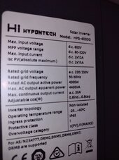
The inverter is 12 amps

The inverter is rated for 12 amps max DC current and isc pv absolute max is 15 amps.
The solar panels are rated at 6.9 amps. Would 2 strings work out so I don't loose a panel or am I pushing it

You haven't told us enough.

The inverter MPPT input spec is not just "12 amps". It will have a spec for max operating current, and another spec for max short circuit current.

The PV panel spec is not just "6.9 amps". It will have a spec for Imp and another for Isc.
 
The problem is the 0.1% of the time can seriously damage your inverter. Never exceed the inverter/MPPT Voc rating. Good units will have some protection, but there is only so much they can do.
Might parallel two strings and hope it doesn't affect current rating
Thanks. I'll reconfigure the wiring
So could I have 2 strings of 10 panels in parallel which would be a max voltage of 480 and 14 amps . Would that be pushing it.
We prefer to design around label specs, not measurement. Specs are tested in a lab with one full sun; field measurement is affected by conditions.
Double-check with measurement.


We have ways to reduce that. 6s2p, with 6s oriented SE and other 6s oriented SW, will have lower peak current. But more operating hours.

Besides, as other said, it is (usually) OK to connect panels able to supply excessive current to inverter. On best day, it goes to waste. On poorer days, you get what two PV strings can deliver, which together will be closer to what inverter can process.


No.

Only SolarEdge optimizers reduce maximum voltage from PV panel. They allow a PV string where Voc x number in series would exceed inverter rating (without the optimisers.) Only for use with SolarEdge inverters.

All others allow maximum voltage through.


You haven't told us enough.

The inverter MPPT input spec is not just "12 amps". It will have a spec for max operating current, and another spec for max short circuit current.

The PV panel spec is not just "6.9 amps". It will have a spec for Imp and another for Isc.
The inverter is 4.4kw
I have 2 strings
11 south and 12 east 250 watt panels
I have 4 DC optimisers on the east panels which help with shading and increase performance of the string .

The 11 panel string help reduce the voltage on the 12 panel string enough to keep the voltage within the inverter tolerance and produce maximum inverter output. When I added another pv panel to the 11 string that's when it all went haywire. So I have disconnected it and everything is performing excellent now
 
Besides, as other said, it is (usually) OK to connect panels able to supply excessive current to inverter.
Going overcurrent is fine, but by no more than the inverter's maximum MPPT power rating. Grid tied inverter's will typically have a maximum DC input rating between 130-200% of their AC output rating but some cheaper units might be limited to 100%.

Might parallel two strings and hope it doesn't affect current rating
Check the specifications of your inverter, it should have a maximum PV power rating. Don't exceed that either. And it will say whether parallel strings are permitted for each MPPT.

Earlier you said:
The inverter is rated for 12 amps max DC current and isc pv absolute max is 15 amps.
The solar panels are rated at 6.9 amps. Would 2 strings work out so I don't loose a panel or am I pushing it
If your solar panels have an Isc (short circuit current) rating of 6.9 A, then they will be fine to place in two parallel strings if your inverter's MPPTs have a maximum current capacity of 15 A.

System design matters, and panels come with various voltage and current ratings, and inverters also have different MPPT current and voltage ratings. You have high voltage, low current panels. Those can be suitable for some system designs and unsuitable for others where lower voltage higher current panels would work better.
 
We prefer to design around label specs, not measurement. Specs are tested in a lab with one full sun; field measurement is affected by conditions.
Double-check with measurement.


We have ways to reduce that. 6s2p, with 6s oriented SE and other 6s oriented SW, will have lower peak current. But more operating hours.

Besides, as other said, it is (usually) OK to connect panels able to supply excessive current to inverter. On best day, it goes to waste. On poorer days, you get what two PV strings can deliver, which together will be closer to what inverter can process.


No.

Only SolarEdge optimizers reduce maximum voltage from PV panel. They allow a PV string where Voc x number in series would exceed inverter rating (without the optimisers.) Only for use with SolarEdge inverters.

All others allow maximum voltage through.


You haven't told us enough.

The inverter MPPT input spec is not just "12 amps". It will have a spec for max operating current, and another spec for max short circuit current.

The PV panel spec is not just "6.9 amps". It will have a spec for Imp and another for Isc.
 

Attachments

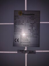
  • IMG_20240615_115550334.jpg
    IMG_20240615_115550334.jpg
    98.2 KB · Views: 15
  • IMG_20240614_153024735.jpg
    IMG_20240614_153024735.jpg
    101.1 KB · Views: 15
"Max input current DC 2x12A"

Looks like it has two MPPT, so put 6s into one 6s into the other for better efficiency (half the current, half the temperature rise.)

If you want to install another 12 panels, you can feed 6s2p into one MPPT input, 6s2p into the other.
I favor 6s2p with 6s oriented SE, 6s oriented SW.

600V max / 1.15 cold adjustment / 48.79 Voc = 10.69, up to 10s is OK.

So you could do 10s2p into MPPT1 & 10s2p into MPPT2.

Inverter is 4000W, PV panels are 250W (estimate 80% +/- under typical conditions) expect 200W.
4000W / 200W = 20 panels suggested to peak at 4000W typically. Assuming all oriented the same.
With strings of 2 angles, 30 panels.
40 panels of 2 or more angles would be a reasonable over-paneling, if you get panels cheap.
Thanks, I have ordered some branch connectors so I will reconfig to 6s2p south and 6s2p east. Can't change the orientation.
I suppose there would be a hugh amount of clipping 10s2p mppt1 and 10s2p mppt2. But would be good in winter and cloudy days
 
If you've got 12 panels facing South and 12 more panels facing East, instead of using "Y" connectors to make 6s2p South, consider using extensions to bring the four 6s to one place and use "Y" to make 6s (South) || 6s (East). Twice.

That way, each MPPT gets the current from South and the current from East; each runs at lower current at any given time, less heating loss and longer life.

Having an MPPT fed two strings of different orientation reduces total kWh harvested about 2% (panels not quite at maximum power point) but electronics runs cooler and may handle more total power if each MPPT by itself has lower wattage rating than inverter.
The trouble is the south string is on a shed at the end of the garden and to bring new cables to the inverter would be quite troublesome as it is located near the east string. I haven't seen that kind of set up but it sounds like a good idea
 
If you've got 12 panels facing South and 12 more panels facing East, instead of using "Y" connectors to make 6s2p South, consider using extensions to bring the four 6s to one place and use "Y" to make 6s (South) || 6s (East). Twice.

That way, each MPPT gets the current from South and the current from East; each runs at lower current at any given time, less heating loss and longer life.
I considered suggesting the same however the current rating of the panels (Imp 6.46 A) is low enough it's not going to matter much. If they are pumping out full power it's probable the inverter will be clipping anyway even with S + E configuration of 6 kW of PV on a 4 kW inverter.
 
I considered suggesting the same however the current rating of the panels (Imp 6.46 A) is low enough it's not going to matter much. If they are pumping out full power it's probable the inverter will be clipping anyway even with S + E configuration of 6 kW of PV on a 4 kW inverter.
Thanks for the input
 
We prefer to design around label specs, not measurement. Specs are tested in a lab with one full sun; field measurement is affected by conditions.
Double-check with measurement.

Though good advice, the double-checking is important.

I have a small 12V, 6-panel setup. My panels clearly state on them that they have a short-circuit-voltage of 19V.

I wondered why my charge controller (which is 12/24/48V compatible) would occasionally go into "standby" even though it was reading PV and the batteries were nowhere near charged. I checked cabling, over-temperature, battery BMS, etc. and could attribute nothing to it. I even fitted temperature-activated, battery-powered ventilation to the box it's in and bought a thermal camera.

Then I realised the cause - the panels are actually giving 22-24V at times.

This is despite them all being in parallel (through long individual runs coming to a combiner box, so I'm able to measure each panel, in effect), being in the UK (not sure how I'm maxing them out with this amount of sun!) and having cable runs long enough that it should be pulling the voltage down somewhat.

For a tiny setup, I was surprised that the panel's specs (and I checked each panel individually, plus the original purchase, plus I retained the manuals) were so far out.

It also doesn't directly correlate with weather - but it mostly only happens on sunny days, not hot days, and I think another poster nailed it - it's to do with temperature CHANGE as much as the actual temperature.

It's more an inconvenience than a danger, and the charge controller is sensible enough to just cut them off briefly and then resume a minute later, but it does mean I'm throwing energy away during that time.

The cabling is otherwise vastly over-specced (which may contribute a little as the voltage-drop is less than expected? But then on a 12V system, my currently voltage drop is probably the worse it will ever be!).

I'm hoping that - as I have planned - when I move to 24V / 48V, the over-spec will not contribute as much in terms of percentage and the controller will handle it more happily, but a panel specifically stating a Voc of 19V? Yeah, don't believe it, no matter how many times it's written all over everything.

Fortunately, my entire system is built on "overspec and under-utilise" principles so everything is able to handle higher voltages and currents than necessary (the charger controller just sees a 12V battery and a 24V solar and gets confused, I think), but I was never expecting a bunch of 19V panels in parallel to be able to hit 24V, especially when they are on opposite sides of the house and at least one is shaded at any time of the day.
 
short-circuit-voltage of 19V
Open circuit voltage. Short circuit by definition is close to 0V

especially when they are on opposite sides of the house and at least one is shaded at any time of the day
In parallel they will all be the same voltage. After a certain minimum brightness I don't think shade affects voltage that much provided bypass diodes are not activated, and they are unlikely to be activated in a parallel setup.

What is the SCC voltage spec? If you can paste the specs / sticker on the SCC you'll get a lot better help and contribute to this thread more. As it is we're pretty much flying blind with what your setup is.

Something really weird is going on if a 12/24/48 SCC is not able to handle 24V. Is it PWM instead of MPPT? An MPPT will happily buck down the input voltage.

Sunny + cold = ideal conditions for solar.
 
FYI
Length and/ or size of conductor has no affect on VOC.
Voltage drop only happens when there is a load on the circuit.
 
I have a small 12V, 6-panel setup. My panels clearly state on them that they have a short-circuit-voltage of 19V.

...

Then I realised the cause - the panels are actually giving 22-24V at times.


How about a picture of the label on the panel?

19V is rather low for Voc, more like Vmp.

22 to 24V is not unreasonable for Voc.

Most SCC accept higher than that, but a couple used for auto or RV do have a low max voltage.

1718979466037.png


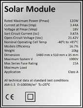
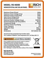
Here's one close to yours:

1718979485488.png
 

diy solar

diy solar
Back
Top