diy solar

diy solar

Checking Chargery voltage measurements

hello everyone,
for the battery powered by battery but connect to exeternal power supply socket, please connect it to BMS according to below picture.
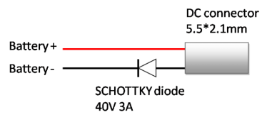
external power supply from Battery.png


  1. The connection is only for 4S battery with BMS8T. the higher battery voltage, the smaller current from battery, so for 8S battery on BMS8T, or BMS16T and BMS24T, the influence can be ignored. with external battery positive and negative cable has a little positive effect. my testing result is as below, i tested the 4 LiPo cell voltage reading on BMS8T. the battery capacity is 2Ah and used for 3 years, has big impedance.
fluke internal battery external battery external AC/DC adapter
cell 1 3.685 3.663 3.665 3.682
cell 2 3.668 3.640 3.640 3.664
cell 3 3.628 3.604 3.604 3.625
cell 4 3.623 3.597 3.604 3.621

Evidently the cell voltage is accurate or as same as actual cell voltage when BMS is powered by external AC/DC adpater, when battery power BMS, whether external connetion or internal connection, the cell voltage is error or has around 25mV difference. Because the balance wire (sense wire) resistance is around 0.05 ohm, but my cell impedance is around 0.1 ohm or more. The result don't mean the solution is uselss,
when test 16S battery on BMS16T, the cell voltage reading is almost as same as with fluke when battery power BMS.
The battery pack can connect to external power supply socket directly, but need a schottky diode.
  1. The schottky current I(av) depends on relay or SSR driven current, the schottky current must be over the two mechenical relay total driven current. for Chargery DCC, 1A is enough.
  2. Move power selector to battery position,
  3. plug the external DC connector to external socket, move power selector to external position, BMS will be powered by external battery connection.
Hope the solution can improve the cell voltage reading.
 
hello everyone,
for the battery powered by battery but connect to exeternal power supply socket, please connect it to BMS according to below picture.
  1. The connection is only for 4S battery with BMS8T. the higher battery voltage, the smaller current from battery, so for 8S battery on BMS8T, or BMS16T and BMS24T, the influence can be ignored. with external battery positive and negative cable has a little positive effect. my testing result is as below, i tested the 4 LiPo cell voltage reading on BMS8T. the battery capacity is 2Ah and used for 3 years, has big impedance.
fluke internal battery external battery external AC/DC adapter
cell 1 3.685 3.663 3.665 3.682
cell 2 3.668 3.640 3.640 3.664
cell 3 3.628 3.604 3.604 3.625
cell 4 3.623 3.597 3.604 3.621

Evidently the cell voltage is accurate or as same as actual cell voltage when BMS is powered by external AC/DC adpater, when battery power BMS, whether external connetion or internal connection, the cell voltage is error or has around 25mV difference. Because the balance wire (sense wire) resistance is around 0.05 ohm, but my cell impedance is around 0.1 ohm or more. The result don't mean the solution is uselss,
when test 16S battery on BMS16T, the cell voltage reading is almost as same as with fluke when battery power BMS.
The battery pack can connect to external power supply socket directly, but need a schottky diode.
  1. The schottky current I(av) depends on relay or SSR driven current, the schottky current must be over the two mechenical relay total driven current. for Chargery DCC, 1A is enough.
  2. Move power selector to battery position,
  3. plug the external DC connector to external socket, move power selector to external position, BMS will be powered by external battery connection.
Hope the solution can improve the cell voltage reading.
Thanks Jason.
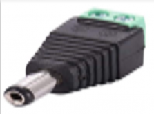
Suggestion: Chargery may want to include an external plug as shown below.
2.1mm_x_5.5mm_barrel_type_male_dc_power_jack_adapter_connector.jpg


GOSH, I miss "Radio Shack" !
schottky diode 40V 3A on Ebay.com
 
Thanks Jason.
Suggestion: Chargery may want to include an external plug as shown below.
2.1mm_x_5.5mm_barrel_type_male_dc_power_jack_adapter_connector.jpg


GOSH, I miss "Radio Shack" !
schottky diode 40V 3A on Ebay.com
I already had some of these plugs thats what I have used with a 18650 battery pack when I first was testing the BMS. I may go back to this or run it it off the main battery and the diode. I see there are few different variations of this diode?
 
Wished i had an accurate meter. So my reading of the comments means there is no benefit to powering the unit externally when i have the 8S pack at 24v, since the difference in cell voltage will be negligible at that current.
Anyone care to put a good meter across a 8S pack and report the cell differences ( @Cal )

What Chargery is saying is not correct. Cell voltage drop may not be negligible when using 24V battery. Cell voltage drop is dependent on the power consumed by the disconnect devices. The greater the disconnect device power, the greater the measurement error. That said, a 24V battery has about half the error as from a 12V battery. But if your disconnect power is twice as much as what I have then my 12V battery error is about equal to your 24V battery error. In my case, I have a small disconnect current of about 30 mA. With that small current, cell 1 has an error of 18 mV. If your disconnect current is 60 mA, you will also see about 18 mV error. If disconnect current is higher yet then errors can be significantly greater than 18 mV. What is your total disconnect current?

Pointing out another Chargery incorrect statement, cell impedance has no effect on this measurement error. This error is only related to the voltage drop in the sense wire. The greater the sense wire resistance (including wire crimp to connector resistance), the greater the error. The greater the current going through the sense wire the greater the error. You should be able to reduce the error by replacing the two end wires of the ribbon cable (the black ground wire and the last wire used) with thicker wires.
 
I would defiantly recommend the diode. I had the external power off but connected to the the BMS. I hooked up a 25 amp load to the off side (on the ground side of the contactor) and was surprised when the load came on. The U1 chip in the BMS is Toast. With the DC to DC connected but not powered, For a short time tried pulling 25 amps. unplugged when i saw smoke. At least the battery side still works

@Solarfun4jim I found that the ISDT BATTGO BG-8S is very accurate.

 
What Chargery is saying is not correct. Cell voltage drop may not be negligible when using 24V battery. Cell voltage drop is dependent on the power consumed by the disconnect devices. The greater the disconnect device power, the greater the measurement error. That said, a 24V battery has about half the error as from a 12V battery. But if your disconnect power is twice as much as what I have then my 12V battery error is about equal to your 24V battery error. In my case, I have a small disconnect current of about 30 mA. With that small current, cell 1 has an error of 18 mV. If your disconnect current is 60 mA, you will also see about 18 mV error. If disconnect current is higher yet then errors can be significantly greater than 18 mV. What is your total disconnect current?

Pointing out another Chargery incorrect statement, cell impedance has no effect on this measurement error. This error is only related to the voltage drop in the sense wire. The greater the sense wire resistance (including wire crimp to connector resistance), the greater the error. The greater the current going through the sense wire the greater the error. You should be able to reduce the error by replacing the two end wires of the ribbon cable (the black ground wire and the last wire used) with thicker wires.
The chargery disconnect is off a 12v output, (so i dont think my 24v applies in this instance)and the relay i intend to use is 8mA at 12v....
So im thinking that because i have no intentions of pushing up into the knees with my charging, then my balance function should 'almost' be redundant anyways. Think i will leave it as is, connected through the sense wires. I will be relying on my BMV712 victron for my true state of play SOC anyways.
Thanks for raising awareness.
A. It hooks to the balance leads B. It will do 8 series. I/E 24 volts. Just a heads up.
 
The chargery disconnect is off a 12v output, (so i dont think my 24v applies in this instance)and the relay i intend to use is 8mA at 12v....
If your two disconnect loads are only 8 mA (or even 18 mA) then you should have no issues.

But just to be clear, the fact that disconnect voltage is 12V and your battery is 24V doesn't mean this "problem" or issue doesn't apply to you. You can't neglect the First Law of Thermodynamics. In other words, load power must equal incoming power (neglecting secondary losses).

For example, if the 12V relays have a combined current of 0.5A, they consume 6W. The 24V battery has to supply 6W to maintain the relay load. The 24V current is:

I = P / V = 6W / 24V = 0.25 A

Whatever the 12V relay currents is, this current is reduced by a factor of 2 in a 24V battery and reduced by a factor of 4 in a 48V battery.

In your case, you may have 20 mA relay current and 50 mA BMS operational current for a total of 70 mA. The 24V current is 35 mA.
Thanks for the explanation Cal. I have two relays at 8mA and one at 25mA giving a combined total of 41mA (2 charge disconnects/1 discharge disconnect)
Thus at 12v consumption is less than 0.5W or 0.025W supplied by 24v battery.
I have no understanding of what the 'operational' current might be, but i don't imagine it will be very high.

Thanks for the insights.
 
I would defiantly recommend the diode. I had the external power off but connected to the the BMS. I hooked up a 25 amp load to the off side (on the ground side of the contactor) and was surprised when the load came on. The U1 chip in the BMS is Toast. With the DC to DC connected but not powered, For a short time tried pulling 25 amps. unplugged when i saw smoke. At least the battery side still works

@Solarfun4jim I found that the ISDT BATTGO BG-8S is very accurate.

I have looked at their products they have a T8 that would balance at 2.2amp per cell that I wasn't sure how it would work out.
 
@JoeHam
Thanks Joe,
I'm totally inexperienced in electrics....so how would you connect the external power input to the battery pack to provide the required 3A
I just assumed you needed the converter to regulate the current to the required 3A???The external power input the the BMS is just fine at 24v. Its within the specification. As far as the 3amp specification, the supplying source only needs to supply up to 3A and much less for a system with a DCC. A LOAD , in this case the BMS will only draw what is needed.
 
I've ordered some of thee below to try a few things.
I am running BMS8T, so plan 1 is to power from NEG & POS off the battery terminals feeding to the BMS.

2.1mm_x_5.5mm_barrel_type_male_dc_power_jack_adapter_connector.jpg
@Steve_S
Hi steve, just looking for confirmation that you have now used these on the chargery main board input, powered directly from your 24v pos & neg terminals? I assume no mishaps, no complications with mixed grounds and no diodes needed?
Thanks.
 
please visit https://diysolarforum.com/threads/c...te-nov-25-2020-ver-4-02-firmware.15122/page-5 Bob finished the testing, the BMS is powered by battery with external power port.
@Chargery
Thanks for the link jason, however i believe bob is using a 4s 12V system with a shottky diode, where as i'm looking for info as regards a 24V system without the diode. If all thats needed is a simple 5A fuse on the positive connection, then that would be fine.
I had thought i'd read somewhere that the 24V battery ground was not compatible with the DC input plug ground, however i dont fully understand this.
 
@Chargery

I had thought i'd read somewhere that the 24V battery ground was not compatible with the DC input plug ground, however i dont fully understand this.

Same question here and I believe the manual says you can power with up to 60v.

A good time for @Chargery to clarify if you can power the Chargery directly from a 24 or 48v nominal battery.

Is it permissible?

Is it a good way to improve accuracy??
 
From my vault of e-mail exchanges with Jason:

NEW BMS’ Extra item to include or have available I the store, it people are going to use External Power they need an adapter for it, either include it or have it on the website. These I believe are ideal, I just received mine so that I can power the BMS from the battery packs own (+) & (-) rather than take the power from the harness. an adapter is easy to get, but add a diode is a trouble, so i don't suggest all users do this on all BMS modles.

Should there be a “filter” or anything extra between this plug & the batteries own +/- ? don't need filter, but a diode is essential.

for the problem, i make many testing with 4S and 8S battery on BMS8T, 16S battery on BMS16T, the testing result is only "power BMS by external socket from 4S battery at 12V" is useful or can avoid the influence of current flow harness. because the current from battery is maximum when 4S battery at 12V. so i don't think it is not essential for other battery or BMS. the root solution is power BMS by AC/DC adapter or by other battery. When power by AC/DC adapter, the cell voltage is very accurate, it is tested by CAL on forum, in fact, when we calibrate cell voltage, the BMS is powered by AC/DC adapter.

As far as cell voltage accuracy, it depends on cell voltage calibration, when calibrate again, the cell voltage reading is improved. power BMS by external socket don't solve the problem. we improved the reference voltage accuracy and changed the cell voltage accuracy testing method after calibration two months ago. now the cell voltage reading is acceptable, it is under 5mv difference compared with FLUKE reading.

as far as current reading, your suggestion is correct, the battery positive and negative cable should be together and short as soon as possible. we updated the current measurement on V4.02, The accuracy is improved, but if it is not stable, need change or add a low pass filter inside of BMS, for different charger, inverter, and cable distance, length, have not perfect solution to solve all problems.

12V off battery terminals apparently need the Shotky resister,
24V up should be ok, from what is gleened. I have asked for a very clear response like for 12V do this, 24V, 48V fo A or B... nope.

I want to put the packs on Batt Terminal power and have the adapters for the plugs. It occured to me though, it may be prudent to put an ON/OFF switch between the plug in and the terminal connection to kill power without having to pull the plug.

1607523625663.png
 
From my vault of e-mail exchanges with Jason:


12V off battery terminals apparently need the Shotky resister,
24V up should be ok, from what is gleened. I have asked for a very clear response like for 12V do this, 24V, 48V fo A or B... nope.

I want to put the packs on Batt Terminal power and have the adapters for the plugs. It occured to me though, it may be prudent to put an ON/OFF switch between the plug in and the terminal connection to kill power without having to pull the plug.

View attachment 29765
I thought i might just put an inline blade fuse of 5A, that way if i want to kill the power i just pull the fuse, plus a little protection also.

If you had to go down the route of an AC adapter, which ones would be recommended for connection 24/7/365 without overheating? Even the best laptop bricks get very warm when used for a few hours.
 
There's also measurement errors with 24V batteries. The magnitude of the error is dependent on how much current the disconnect devices draw. If you use mechanical relays then you will see significant errors. The best remedy is to use external power input along with the Schottky diode.
 
There's also measurement errors with 24V batteries. The magnitude of the error is dependent on how much current the disconnect devices draw. If you use mechanical relays then you will see significant errors. The best remedy is to use external power input along with the Schottky diode.
Cheers Cal, but on a 24V RV system, you don't really have external power in the true sense of the word. I believe i read somewhere that if powering the 'DC input' connection from the 24V battery pack, then you would not need the schottky diode. The diode is only necessary for 12V systems, but happy for you to correct me on this. If you power an AC adapter from the inverter, then in reality, it is not truly an external power input. We seem to be going around in circles.
 
Not true. It doesn't matter what size the battery pack is (12V or greater), you absolutely need a schottky diode.

You don't need the diode if the external supply is isolated from battery (no common ground connection).
 
To tell the truth, I'm not really sure what the Schottky diode does in this application .... but since it was indicated in the manual I went ahead and installed it on the 4S pack. They are cheap and it was pretty easy to install.

Can someone explain why it would be desirable on a 12V pack ... but not on a 24 or 48? What is the purpose of the diode?

I do know that the Chargery BMS will have to down regulate power of 24V or higher. Might be easier to just use an external DC-DC converter to down regulate the voltage and take that heat load out of the BMS.
 
Not true. It doesn't matter what size the battery pack is (12V or greater), you absolutely need a schottky diode.

You don't need the diode if the external supply is isolated from battery (no common ground connection).

@Cal
Right Cal, now we are getting somewhere (y)

Im presuming the same 40v 3A schottky diode will do for the 24v DC connection?

What im trying to ascertain, is, if you have the 24V pack as the only power source, what is the most efficient way of connecting it to the BMS to acheive the greatest possible voltage accuracy? Direct seperate connections (not harness wires) with an inline fuse and schottky diode?

Appreciate your input.

edit ps...i'm not interested in SOC or balance function of BMS, only really accurate voltage measurement.
 

diy solar

diy solar
Back
Top