Hi,
Possibly both, although it does say in the specs 0-100A. Which to me would imply not.
I bought this:

 www.aliexpress.com
It says in the specs 0-200A, but in on one of the pics it mentions a relay which it says will "automatically disconnect if battery is full discharged or fully charged". So it must measure current flow in either direction.
dRdoS7
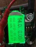
Does this meter show charge and discharge? Or is it only one way?
Bob
Possibly both, although it does say in the specs 0-100A. Which to me would imply not.
I bought this:
19.73US $ 20% OFF|Dt24p 1000v/200a Ips Digital Display Dc Power App Voltmeter Ammeter Battery Capacity Tester Fuel Gauge Voltage Detector Meter - Voltage Meters - AliExpress
Smarter Shopping, Better Living! Aliexpress.com
It says in the specs 0-200A, but in on one of the pics it mentions a relay which it says will "automatically disconnect if battery is full discharged or fully charged". So it must measure current flow in either direction.
dRdoS7