John Frum
Tell me your problems
- Joined
- Nov 30, 2019
- Messages
- 15,230
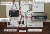
I’m new to all of this, How, if at all, would this work with a Inverter/Charger so I can have shore power also. Will it matter if my van battery is AGM and the house battery is Lithium? Thanks
Your van's starter battery is AGM?
Have not seen that before.