diy solar

diy solar

Active balancer, make it smart!?

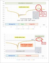
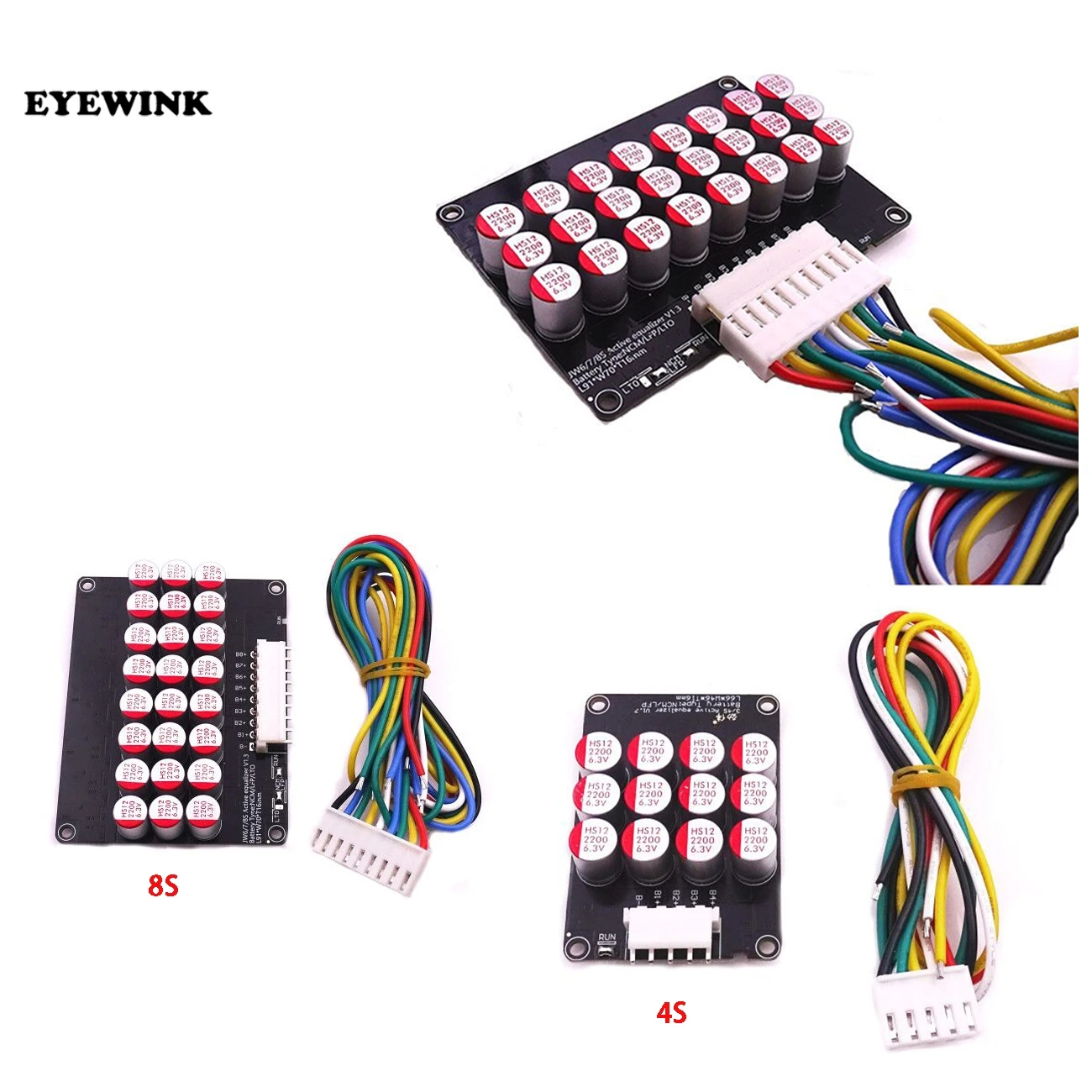
As promised, here is one option how to control the Heltec active Balancer using the BMV712 Battery Monitor........I will show more circuit diagrams on this subject later this week.
Regards Hans
p.s. it is easy to modify this circuit for 24 V ....36 V ..... 48 V Systems, using the appropriate balancer from Heltec
View attachment 96541

As promised, here is another circuit diagram for the control of the Heltec active balancer to make it smart. I tested the VP2106 MOSFET interface
I dont't see the need for a relay. On the balancer there is this contact, that either switches to GND or to +. Instead of a relay, a mosfet or if you are super scared, an optocoupler would probably do the trick.
Sorry, but this interface does not allow to switch to ground or plus. An optocoupler is OK.
I played around for a while and found a solution to use a P Channel MOSFET. When I tried to post the circuit diagram something went wrong. Once I am back on my PC I will send the circuit diagram.....
 
*Edit

Update on customized version from HANKZOR:

The customized version is ready, have just ordered it. Shipping will take 9-16 days. They said the customisation they did was they changed the resistance. They raised it to about 3.4V (means below that it will go to sleep, no balancing anymore and only 0.1mA consumption), in the lab they tested 3.43V, small error is normal.
They only made one piece so far.
Will update once i have tested it.
Here is the heavy question. Is this device watching on average voltage for cells to determine when to awake. And what is the delay for device to boot.
If it is looking after average Voltage to awake this could lead under charging that one cell can drastically shoot over 3.650 and still keep idling because average cell voltage is not hitting calibrated limit.
Easy way to test this out is to apply to one lead cell voltage that will exceed settings you set.....and you watch on this battery cell and cell average and see if it wake up. I have rejected many Chinese balancers because they are looking for average voltage and not single cell to wake up and start bringing down cell that has drifted.
 
Easy way to test this out is to apply to one lead cell voltage that will exceed settings you set.....and you watch on this battery cell and cell average and see if it wake up. I have rejected many Chinese balancers because they are looking for average voltage and not single cell to wake up and start bringing down cell that has drifted.
Will perform that test once it has arrived.

I am not sure how they work, i suppose @Hans Kroeger can probably fill you in on that.
There is also a YouTube video which seems to explain how these balancers work (check 1st or 2nd page of this thread), haven't watch it yet myself.

Do you have the same capacitor balancer model? Have you ever performed the test, 3 cells under 2.9V and one cell above? What was your observation?

In this customized version i asked them to raise the balance start voltage from 3.0V to 3.4V.
Below specs from stock product
IMG_20220606_134011.jpg
Means also not far below 3.4V it goes to sleep, 0.1mA quiescent current.
Reading the stock balancer specs it looks like they watch single cell voltage.

They already sent it this morning, now 9 -16 days till it arrives.
 
Last edited:
As promised, here is another circuit diagram for the control of the Heltec active balancer to make it smart. I tested the VP2106 MOSFET interface

Sorry, but this interface does not allow to switch to ground or plus. An optocoupler is OK.
I played around for a while and found a solution to use a P Channel MOSFET. When I tried to post the circuit diagram something went wrong. Once I am back on my PC I will send the circuit diagram.....
Here is the direct interface to control the balancer via a P MOSFET, in order to eliminate the relay.
I have tested the circuit.
Balancer Control a.jpg

The following circuit shows a basic example how to control the balancer using a comparator to measure the total battery voltage. The components can be easily chosen such, that the balancer will turn On at 13,5 V and turn Off at 13,4 V.
Balancer Control b.jpg

Here is the exact circuit, which I intent to set up and test:
Balancer Control c.jpg

I tested the balancer being continuously turned on during charge and discharge cycles. If the balancer gets enough time to bottom balance the cells after discharging, it will result in a temporary overshoot of drifted cells at the end of the charge. It is mandatory to turn the balancer off at times when not charging. Here are some test data to show this effect:

Balancer On Off data.jpg

I hope this answeres at least some of the above questions......
 

Attachments

  • Balancer On Off data.jpg
    Balancer On Off data.jpg
    351.4 KB · Views: 131
This looks very promising Hans.
By the way, which software are you using to draw these nice schematics?
 
*Edited

We could organise our smart solutions into following two groups:

Smart solutions for a battery with matched cells -> Switch active balancer ON-OFF in regard to battery voltage

Smart solutions for a battery with unmatched cells -> Switch active balancer ON-OFF in regard to cell voltage

MATCHEDUNMATCHED
1. Charge controllers,
smart shunts with a relay port
2. Off-the-shelf LVD modules
3. Custom circuits

1. R Pi controlled switching
2. ESP controlled switching
 
Last edited:
Will perform that test once it has arrived.

I am not sure how they work, i suppose @Hans Kroeger can probably fill you in on that.
There is also a YouTube video which seems to explain how these balancers work (check 1st or 2nd page of this thread), haven't watch it yet myself.

Do you have the same capacitor balancer model? Have you ever performed the test, 3 cells under 2.9V and one cell above? What was your observation?

In this customized version i asked them to raise the balance start voltage from 3.0V to 3.4V.
Below specs from stock product
View attachment 97430
Means also not far below 3.4V it goes to sleep, 0.1mA quiescent current.
Reading the stock balancer specs it looks like they watch single cell voltage.

They already sent it this morning, now 9 -16 days till it arrives.
No i have not yet have one of this to test but i would love someone else to do it.
After top balance is done provoke one of the cells above threshold to find out if it is looking after average cells voltage or single cells voltage to wake up and balance again. And what is the delay and how many times it looks after all cells in Series before module algorithm is reading balance out of state and is time to wake up. And definitely interested if this is fully automatic or it needs periodic users control over turning on and off.
Making couple tests and watching how big is overshoot when balancer turns on will lead you quickly how accurate is.
On some balancer I have been testing they where 0.26-0.3 V and where using average voltage for reference and over 140 seconds to respond. On well assembled battery pack this was alarming but on grade B cells this was bad design to trust on automatic balance no balance scenario. Using average voltage for reference will lead one cell to peak over 3.65 and still make average not to trigger balancing ( because it was designed after average Voltage lookout).
I have this particular balancer already, the stock unmodified version.
I can describe you what happens from just right now. My battery stopped charging at 13.9V, with an 18mV deltaV. Active balancer was switched off. I switched the balancer on, instantly i saw already a voltage difference drop. Solar charging started automatically again, just 1w, to supply balancer (i see this via my tk15 coulomb counter). Now after a few minutes deltaV is 2-3mV, solar charging stopped again since balancer stopped but still has an idle consumption of about 15mA. BMS balancing was off all the time btw. Now i switch the balancer off again.
So it is definitely not average voltage but voltage difference which triggers the balancer. It stops if deltaV is less than 5mV, usually around 1-3mV in my case. They guarantee less than 5mV.

Specs sheet
IMG_20220606_184012.jpg
IMG_20220606_183955.jpg
 

Attachments

  • Screenshot_2022-06-06-18-37-39-125_com.alibaba.aliexpresshd.jpg
    Screenshot_2022-06-06-18-37-39-125_com.alibaba.aliexpresshd.jpg
    264.1 KB · Views: 9
Last edited:
I have this particular balancer already, the stock unmodified version.
I can describe you what happens from just right now. My battery stopped charging at 13.9V, with an 18mV deltaV. Active balancer was switched off. I switched the balancer on, instantly i saw already a voltage difference drop. Solar charging started automatically again, just 1w, to supply balancer (i see this via my tk15 coulomb counter). Now after a few minutes deltaV is 2-3mV, solar charging stopped again since balancer stopped but still has an idle consumption of about 15mA. BMS balancing was off all the time btw. Now i switch the balancer off again.
So it is definitely not average voltage but voltage difference which triggers the balancer. It stops if deltaV is less than 5mV, usually around 1-3mV in my case. They guarantee less than 5mV.

Specs sheet
View attachment 97451
View attachment 97452
This one has no Bluetooth dongle and no access to make any changes?
 
This one has no Bluetooth dongle and no access to make any changes?
Sorry what do you mean?
That's the one i use as well the one which was customized, the one I talked about in the post you quoted.
 
Neey is one of balancers i have decided to go against with some of my friends who insisted and always had problems with top balancing.
This one is looking after average cell voltage and 140+ seconds look with 4 pings to the average cell voltage to make decision to awake and continue balancing where in this case some cells could be easily peaking over max desired voltage for quite some time before it will go online and balance. Chinese Neey users be warned.
 
My next toy to play will be JK balancer 5A and 10A for benchtop observation. Will post once i have them received. When people know how some active balancer are working, they will have better understanding how to manage them in best practices possible to keep battery well balanced.
 
My next toy to play will be JK balancer 5A and 10A for benchtop observation. Will post once i have them received. When people know how some active balancer are working, they will have better understanding how to manage them in best practices possible to keep battery well balanced.
Here the YouTube video i referred to before.
 
@Visusolar you definitely draw my attention so I'm going to follow you on this forum. Thank you for responding to my posts.
 
Max, thank you for the link to this video. I believe it answers all previous questions about the basic function of the balancer.
You are welcome but the credit goes to RCinFLA who found and shared it first. Just now i watched it for the first time myself ?, yes it explains a lot!
 
My next toy to play will be JK balancer 5A and 10A for benchtop observation. Will post once i have them received. When people know how some active balancer are working, they will have better understanding how to manage them in best practices possible to keep battery well balanced.
The standalone JK active balancers dont have the ability to turn off below 3.4V
You can use the equilization voltage setting (delta V) to act as a 3.4V on/off proxy by setting equilization voltage to 20mV this minimises the balancer turning on in the flat of the voltage graph. With this setting I have balanced a 300AHr 16s LiFePO4 offgrid pack (1-4 cell each <200mV when pack =55V due to a non smart balancer left on 24/7) over 2 months with a 2A JK active balancer connected 24/7
 
I just wanted to say thanks to all of you guys who talked about this active balancer. The videos are great, and they convinced me to order one. The principle of these balancers seems to be clever and simple.
I feel confident that a simple comparator can be used in the way Hans showed to turn the balancer on and off at desired voltages.
Yes very clever and simple indeed.
Look around AliExpress a bit, you can find them below 10usd. There are also some new designs (just saw it for the first time) like this one
They also start balancing later (3.25v) which sounds like an improvement.
Or the well known v1.7 ones
Maybe also get a simple lvd (mine is still stuck with the shipping company)
 
Just came across this excellent video! This seems already like an easy cheap quick almost ready made solution i was looking for! ?

Just need to figure out how to hook it up on the RUN solder joint!

*Edit: this analog solution works (read further) and there are cheaper and less energy hungry modules out there in compare to the one used in the video.

My order of this board showed up from eBay, hooked it up to the bench power supply at 12v no display no relay clicking, took about 1-2w, didn’t feel anything warm on it. Tried cycling power a few times and it did wake up for some odd reason, display flashed as I had no voltage to monitor, heard the relay click. Cycled power a few more times and it seemed very intermittent in turning on.

While I was in the process of hooking up another 12v supply to the voltage sensing port she let the smoke out a surface mount resistor upper left corner popped. Current on the PS went to zero.

Bummers, I think the board was knackered from the start I had proper polarity and check voltage on the board multiple times, I’m out $11.50.
Sorry to hear that! Things breaking down is usually a bummer, everyone knows that experience. Something like this didn't happen just once to me ? but well that's the nature of things, what is born -> dies, what is created -> breaks down. Though being able to accept that is usually a challenge.
A similar lvd board like yours, one with even a nice blue LCD screen broke also down during trying to set it up.. couldn't use it even once. It still rests it in my electronic graveyard.
 
IMG_20220608_200938.jpgIMG_20220519_210800.jpg
Would really like to know how these two compare to each other. As well what this "touch" could be?? I saw one brave soal already ordered one of these new and comparatively slightly cheaper capacitive active balancers. Not much info about it available yet.
 

diy solar

diy solar
Back
Top