diy solar

diy solar

Active balancer, make it smart!?

Sorry, I need a picture of the top copper traces of that module to even attempt to figure it out.
Question, would it also be possible to just exchange the positive and negative of the active balancer as marked in the picture with the positive and negative of the load output?

Or the negative load to b- and the positive to run and B4 disconnect?

Or does this not work because of the blocking Diode on the lvd module?
IMG_20220518_224852.jpg
 
Question, would it also be possible to just exchange the positive and negative of the active balancer as marked in the picture with the positive and negative of the load output?

Or the negative load to b- and the positive to run and B4 disconnect?

Or does this not work because of the blocking Diode on the lvd module?
View attachment 95048
I don't know the answer to this. Maybe others can help.
 
Question, would it also be possible to just exchange the positive and negative of the active balancer as marked in the picture with the positive and negative of the load output?

Or the negative load to b- and the positive to run and B4 disconnect?

Or does this not work because of the blocking Diode on the lvd module?
View attachment 95048

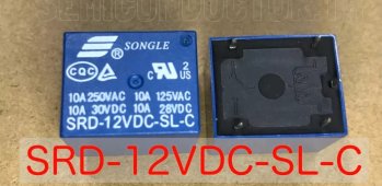
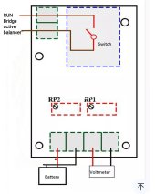
IMO no modification to that active balancer is needed other than wire a relay contact device to the RUN pins.

The device in the video seems simple enough, depending on your cells you can adjust the “on” voltage to catch that pesky cell and start balancing before it gets too high.
 
I don't know the answer to this. Maybe others can help.
Thanks , hopefully someone else can answer.

By the way the yx-x0001 module seems to be not good, goes into hysteresis, emits screening sounds as well draws much more power in reality, up to 87ma.
So i won't order it.

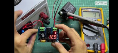
Do you think the 609 module is worth buying, did you notice any issues? Or is there a better lvd module you know of?
How much ma does the 609 draw in reality when lvd is activated/ the relay is open but display switched off?
 
Last edited:
I don't know the answer to this. Maybe others can help.
Or could I get just a 12v relay and activate the relay with the load output!? Does that work? They are pretty cheap so i don't have to tamper with the lvd module.
IMG_20220518_233442.jpg
Connect load output to external relay and external relay to RUN pins. Will that work?

Got the idea from a YouTube video but i don't understand what he says. But it looks like it works.
Screenshot_2022-05-18-23-38-50-070_org.mozilla.firefox.jpg
 
Last edited:
Why is a secondary relay needed? There shouldn’t be much of any current through the RUN “jumper”.
 
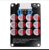
I have not examined the Heltec capacitor balancer mself but it appears to be similar to a serial-parallel-serial balancer. I have not had much interest in it as I would not trust 6.3v rated electrolytic caps reliability, subjected to potentially high ripple currents to expensive battery cells.

Because of the series resistances involved in MOSFET's and capacitors it will likely do more to misbalance cells when all cells are below 3.4v.

This video has an explanation.

 
Last edited:
I just have a simple voltage sense circuit controlling a relay which is connected to the RUN tabs. At 27 V it turns balance on and at 26.8 V it turns off. When I get around to tidying things up I'll try and use the R PI to control the Heltec's.
 
I just have a simple voltage sense circuit controlling a relay which is connected to the RUN tabs. At 27 V it turns balance on and at 26.8 V it turns off. When I get around to tidying things up I'll try and use the R PI to control the Heltec's.
Sounds great, would you mind sharing the schematic of your solution with us? Is it simpler than these lvd modules like the 609?
 
Why is a secondary relay needed? There shouldn’t be much of any current through the RUN “jumper”.
Secondary relay is there to just open or close the RUN connection without inducing any energy/ without potential energy behind/ without connection to the battery. Maybe i got it wrong but if you would directly connect the load outputs you would cause a short.
 
I have not examined the Heltec capacitor balancer mself but it appears to be similar to a serial-parallel-serial balancer. I have not had much interest in it as I would not trust 6.3v rated electrolytic caps reliability, subjected to potentially high ripple currents to expensive battery cells.

Because of the series resistances involved in MOSFET's and capacitors it will likely do more to misbalance cells when all cells are below 3.4v.

This video has an explanation.

If the video, right now downloading, has an explaination why there could be potentially high ripple currents or why these caps are potentially dangerous then please forget this question.
It seems you know something which is kept hidden by those balancer manufacturers, why could these caps potentially be harmful to ones cells?

Yes it is proven fact that any kind of balancer so far causes misbalance in the flat curve area. No kind of balancer has seperate reliable coulomb counters for each cell so it is understandable that they will cause more misbalance than balance below 3.4v.

That's the whole point of this thread, to avoid that not smart/ not desirable behavior through finding automated "smart" solutions to switch the balancer on above 3.4v and off below 3.4v.
so far this was done by hand, now we look for simple reliable cheap ((otherwise there are better (single cell monitoring) solutions like a jk BMS etc)) automatic solutions.
 
I have not examined the Heltec capacitor balancer mself but it appears to be similar to a serial-parallel-serial balancer. I have not had much interest in it as I would not trust 6.3v rated electrolytic caps reliability, subjected to potentially high ripple currents to expensive battery cells.

Because of the series resistances involved in MOSFET's and capacitors it will likely do more to misbalance cells when all cells are below 3.4v.

This video has an explanation.

thank you for the video!

they claim that the heltec capacitive active balancer operates with the following mode:

there's a capacitor for each cell. first, Cell 1 charges Capacitor 1, Cell 2 charges Capacitor 2, etc..

then all the capacitors are disconnected from cells, then connected to each other in parallel. this equalizes the voltages of the capacitors.

then the capacitors are disconnected from each other, and reconnected to the cells.


by virtue of parallel balancing the capacitors, the cells will also be "virtual parallel balanced" in a switching manner.

unsure how bad the ripple situation is.

it makes a lot of sense to me. thanks again for the video.

active balancing is definitely a useful ability :) but cannot replace proper design ;)

one lingering curiosity... there are quite a few capacitors (read: more capacitors than cells). i wonder if they are being used parallel to reduce load on each one, or being used as a baton pass type thing..
 
not trust 6.3v rated electrolytic caps reliability, subjected to potentially high ripple currents to expensive battery cells.
may i ask more about the situation where you expect maximum ripple current?

e.g. battery is serving a single phase inverter, has current ripple, leading to damage of balancer?

6.3V is much higher than the 3.65V maximum i expect from a single LFP cell.

but if even two cells were series connected to a single cap, of course that could easily exceed the rating.

according to the video, the capacitors are connected to a single cell, disconnected, then parallel connected with all other capacitors.

if the circuit is designed properly, it should be electrically impossible to apply more than a single cell voltage to a given capacitor?

perhaps in a potential "shoot through" condition where the cells are connected to the capacitors at the same time as the capacitors are being parallel balanced?

thanks again for all that you share.
 
I just have a simple voltage sense circuit controlling a relay which is connected to the RUN tabs. At 27 V it turns balance on and at 26.8 V it turns off. When I get around to tidying things up I'll try and use the R PI to control the Heltec's.
That is exactly what my unit is doing without an external microcontroller. The VOUT terminals that are connected to the 'RUN' pads of the balancer are closed at 54.4 V and opens at 53.6V (my battery pack is LifePo4 16S1P). These trigger points are set using the M609 pushbuttons. The modification isolates the VOUT terminals from the rest of the M609 circuit. The added 48V relay disables the M609 if there is no solar power.
 
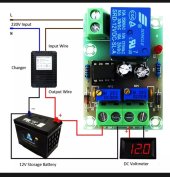
I suppose this would be a fitting module for the purpose of simply opening and closing the RUN bridge without having to do any mods on the module nor active balancer!

Xh-m601
Pro: super low self consumption at 0.3ma!
(There are also other similar modules like xh-m602 with display and buttons for almost the same price but consume 20 to 50ma, about 0.2 to 0.5W)
Con: difficult to adjust lvd etc
How to adjust

Has someone experience with this module?
IMG_20220519_074902.jpg


IMG_20220519_091206.jpg
 
Last edited:
Secondary relay is there to just open or close the RUN connection without inducing any energy/ without potential energy behind/ without connection to the battery. Maybe i got it wrong but if you would directly connect the load outputs you would cause a short.

Open and closing a jumper should have minimal/zero current through it.

As for only having the active balancer running when SCC is pumping into the cells. IMO id much rather have the active balancer running based on a voltage set point ie system voltage is higher than a certain point that means the SCC is on.
Soon as the SCC is off voltage will bleed down, this added time of active balancing while cell voltages drop will only help balance the cells.

Finding that set point where active balancer isn’t running too long will be key. Don’t want it running too long nor too short.
 
Last edited:
Open and closing a jumper should have minimal/zero current through it.

As for only having the active balancer running when SCC is pumping into the cells. IMO id much rather have the active balancer running based on a voltage set point ie system voltage is higher than a certain point that means the SCC is on.
Soon as the SCC is off voltage will bleed down, this added time of active balancing while cell voltages drop will only help balance the cells.

Finding that set point where active balancer isn’t running too long will be key. Don’t want it running too long nor too short.
For me personally key won't be whether there is solar energy or not nor how long or short it balances but the voltage range in which it operates. I intend to have it switch on at about 3.43V cell average and switch off again at about 3.4V if possible. Once the pack is balanced the balancer doesn't work anyway anymore and their quiescent currents are pretty low so time is no issue for me. usually my active balancer gets my pack into balance again within 2-10min. It works really fast!
I have to play around a bit to find the sweet on-off voltage spots for my battery pack and usage. I just ordered a xh-m601 and now starts the waiting game again. Pretty cheap, 0.81usd inclusive shipping. Hope it works reliable enough. Will later post my experience with it if there is interest.

I did let my balancer running for months and it totally unbalanced my whole pack. The difference between my cells was 20 to 40% capacity. Since i am using daily high currents my cells (will have to check their contacts again) get easily out of balance so having an active balancer really speeds things up (BMS balancer is ultra slow). So i hope the xh-m601 will prevent any issues and automatice balancing.
 
Last edited:
For me personally key won't be whether there is solar energy or not nor how long or short it balances but the voltage range in which it operates. I intend to have it switch on at about 3.43V cell average and switch off again at about 3.4V if possible. Once the pack is balanced the balancer doesn't work anyway anymore and their quiescent currents are pretty low so time is no issue for me. usually my active balancer gets my pack into balance again within 2-10min. It works really fast!
I have to play around a bit to find the sweet on-off voltage spots for my battery pack and usage. I just ordered a xh-m601 and now starts the waiting game again. Pretty cheap, 0.81usd inclusive shipping. Hope it works reliable enough. 0
You just need to be above knee. Below this the voltage is flat so balancing seems pretty useless to me.
 
You just need to be above knee. Below this the voltage is flat so balancing seems pretty useless to me.
I agree in general but why i start a bit earlier is because I usually have a runner cell. So i want to slow down that cell early on. Further since this is only cell average there will be a cell which is even far higher than 3.43V once the balancer kicks in. I probably have to start even lower. Let's test and find out once it arrives.

A jk BMS would really be the best because it manages the cells individually but the new 4s version is overkill for my 53ah pack and still too pricey for me. I wait for a cheaper, lower current version. But maybe the xh-m601 will already do the tasks i am looking for well enough!?
 
I really wonder why no active balancer manufacturer hasn't yet integrated an adjustable or even fixed balance cell voltage start and stop yet!? They should know that leaving that thing on permanently disbalances the pack. They could even do it so that each cell starts stops separately at about 3.45v or so. Shouldn't be that complicated to do. They already have a limiter so they just would have to set the low point higher. their high point 3.6v is already good enough.

Or maybe there is a smart knowledgeable person here who can figure out which resistor has to be replaced to increase the limiter voltage point when the balancer stops working. So we could do a diy mod!
 

diy solar

diy solar
Back
Top