diy solar

diy solar

Compress or not, flexible busbar or not

My cells have the welded studs. I couldn’t see how the terminal could rotate in the case. At 85inlbs the serrated nut is thoroughly grabbing onto the busbar but the busbar still spins on the terminal bed by hand if I tried hard enough to spin it. The busbar flexes in the middle when I do this. Makes me think it’s certainly not to tight..
I rechecked my torque and still 85inlbs.. don’t know what the torque spec should be because the cell spec sheet I was emailed was for the cells without the welded studs. And for those I think it was 35inlbs so they don’t strip out
 
About the rods used in these battery "cases", should they be stainless steel or zinc plated steel is perfectly OK?
Asking as there is a huge price difference (6x) between them...
(In any case, they will be enclosed in rubber tubing)

Thanks in advance for all opinions!
 
don’t know what the torque spec should be
Nothing really changes by the use of the fastener; the torque is specified by the type of material and the size. Lots of charts online, but again, we really don't know the material they used. I thought they were stainless, but now they look zinc plated after close inspection. Either way, I'll be a bit conservative since I don't care to twist one off.
 
About the rods used in these battery "cases", should they be stainless steel or zinc plated steel is perfectly OK?
Asking as there is a huge price difference (6x) between them...
(In any case, they will be enclosed in rubber tubing)

Thanks in advance for all opinions!
Zinc plated should be just fine, and much easier on your pocketbook.
 
Nothing really changes by the use of the fastener;
Are you saying there’s no difference between welded studs and threads? I have read 35inlbs for threads and 85inlbs for studs. Searched on here for torque for welded studs and 85inlbs was the result. That wasn’t my max, it was the torque recommended
 
Are you saying there’s no difference between welded studs and threads? I have read 35inlbs for threads and 85inlbs for studs. Searched on here for torque for welded studs and 85inlbs was the result. That wasn’t my max, it was the torque recommended
I'm saying that if you have a 6mm fastener, it is a 6mm fastener. Since your fasteners are welded, you aren't concerned with torque for aluminum. Steel and stainless have different strengths, so it matters which you have.
 
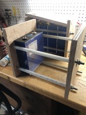
That is basically what I did, my cells are set at 640psi and mounted on vibration dampers. I go off road quite a bit for work and they have been holding up for about a year and a half. If you are heating you have air space under the cells for air circulation as well.
Hi @S Davis. I have a further question: Do you have anything supporting the cells on the bottom of the compression rig? Or are they directly resting on what looks like an aluminum plate in the photo?

I really like your setup, and I'm trying to design something similar in my build. As that's a very heavy load for my camper I was thinking of placing it closer to the cab and having the two water tanks on each side, this way I have the best weight balance. But I want the cells to be suspended a bit from the floor so that in case of any leaks or flooding in the camper they don't short out. Hopefully, it will never happen, but better safe than sorry. You also have the enclosure on the outside that can be sealed, but I feel like that adds unnecessary weight and I'm looking for something alternative.
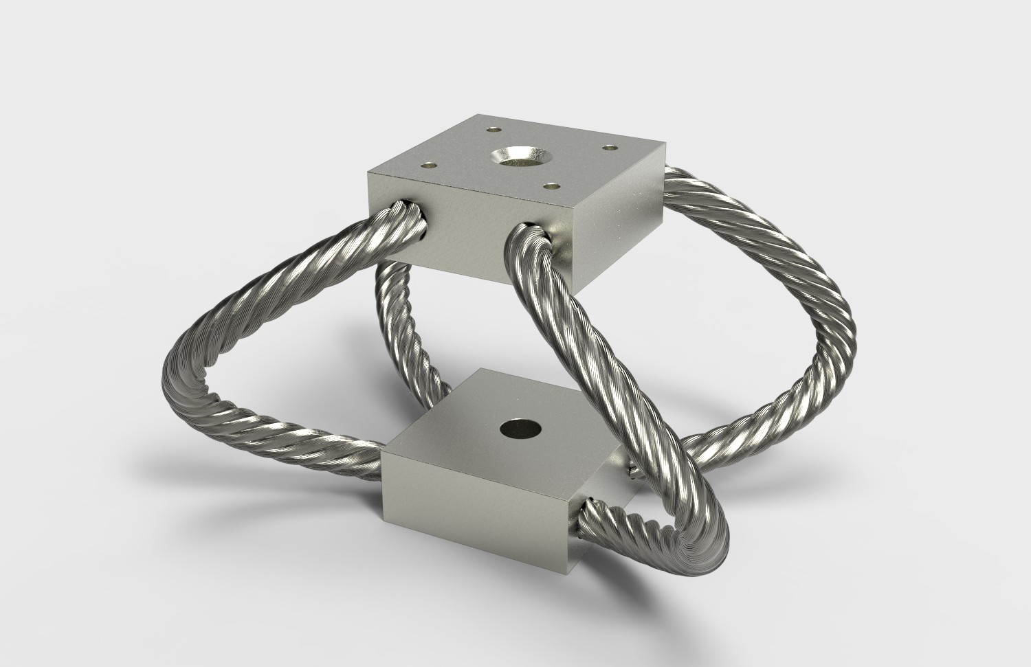
I have no idea about the availability of these isolators, but I have seen them on various pieces of equipment and they seem to work quite well. The good news is that you can make them yourself if you are willing to do a bit of experimenting with cable size and loop diameter/count.

https://www.isolator.com/isolators/sm-series/

IDC-SM-Series-Reduced-1.528.jpg
 
Hi @S Davis. I have a further question: Do you have anything supporting the cells on the bottom of the compression rig? Or are they directly resting on what looks like an aluminum plate in the photo?

I really like your setup, and I'm trying to design something similar in my build. As that's a very heavy load for my camper I was thinking of placing it closer to the cab and having the two water tanks on each side, this way I have the best weight balance. But I want the cells to be suspended a bit from the floor so that in case of any leaks or flooding in the camper they don't short out. Hopefully, it will never happen, but better safe than sorry. You also have the enclosure on the outside that can be sealed, but I feel like that adds unnecessary weight and I'm looking for something alternative.
The cells sit on two pieces of 3/8” all thread with 1/2” pex pipe covering them.
 

Attachments

  • F0AE6F79-D5D2-461E-83D5-5F01526444F8.jpeg
    F0AE6F79-D5D2-461E-83D5-5F01526444F8.jpeg
    145 KB · Views: 38
Oh, interesting, so one of the bottom rods is not on the side but actually below. Really clever and makes perfect sense now. Thanks!
I thought you were asking about his shock isolators. One of his photos showed them. They should be important in a mobile application to keep high frequency vibration from disturbing the batteries.
 
I thought you were asking about his shock isolators. One of his photos showed them. They should be important in a mobile application to keep high frequency vibration from disturbing the batteries.
Those are important as well, and I'm going to use it, but I wanted to know how the cells are supported on the bottom and the single rod is great idea
 
That also tend to be very low impedance devices, which require special amplifiers to use. I'm not saying you couldn't use them. I have a small pile of them that I got surplus. I'll check them to see if I could get them to work.
Hi!

Were you able to make it work?
I haven't bought them (yet) given your thoughts, but the diagram to make it works seems quite easy with an Arduino (I'll try to dig it).
My idea is to have a log / graph crossing temperature, SOC and pressure in a spring loaded "case".
That would be used as an alarm if readings jump out of the ordinary
 
The cells sit on two pieces of 3/8” all thread with 1/2” pex pipe covering them.
Hi!

Is this for stationery application or mobile?
Because if mobile, given the cell's weight, I believe rubbing due to vibration could lead to PEX's failure
 
I thought you were asking about his shock isolators. One of his photos showed them. They should be important in a mobile application to keep high frequency vibration from disturbing the batteries.
Do you have any info on the kind of rubber shock isolators or vibration frequencies?
For me, this makes a lot of sense, but I don't have any data to make a plan in order to mitigate this problem.
 
Hi!

Is this for stationery application or mobile?
Because if mobile, given the cell's weight, I believe rubbing due to vibration could lead to PEX's failure
It's for a mobile application, he talked about it before. I don't think it's a problem since the cells are compressed with the enclosure the rods will vibrate the same as the cells, so no rubbing in theory. Plus he has dampening mounts on the whole enclousure which reduces at least some of it.
 
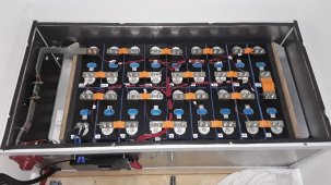
This is my now complete 18S eve280k battery, compressed with 6x threaded rods with nylon sleeve/ 18x 32x20mm springs - 3x on each rod / 20mm HD form each end, currently total approx 300kgf to allow it to settle, after a week will up compression to around 400kgf this will allow for expansion in the region of 12mm before compression goes over the recommended kgf.IMG-20221101-WA0007.jpeg
 
This is my now complete 18S eve280k battery, compressed with 6x threaded rods with nylon sleeve/ 18x 32x20mm springs - 3x on each rod / 20mm HD form each end, currently total approx 300kgf to allow it to settle, after a week will up compression to around 400kgf this will allow for expansion in the region of 12mm before compression goes over the recommended kgf.View attachment 119195
Looks well done. Is that a t-class fuse. Looks like an ANL.
 
I’m not seeing any movement/expansion from my CATL cells. Although highest I charged them up to was 3.53v and 60amps discharge max. When measuring the spring compressed length at 25% SOC and 95% SOC there is no difference in the spring length. I am not compressing the cells to 660lbs either. The springs I’m using are supposed to be compressed one inch to 2.175 from 3.175 inches to achieve 640lbs. I only compressed the springs 3/4” instead of an inch. I did that because it seemed to be plenty tight enough. And as I said there is no expansion happening at all with this amount of compression. Whatever that amount is, it’s less than 640lbs.. Still good to have the springs in place to have some good compression and if the cells ever did decide to unexpectedly expand they could without being over compressed. Flexible busbars also good to have just in case there ever was expansion so the bms continues to read the cells correctly..
 
Last edited:
660lbs seems crazy per cell, agree with you on a bit less and I'm happy too. For my set up of two rows it would be 1220lbs / 600kg!!
I put HD foam at each end as my clamp is two rows together, this then allows for either row a bit of movement seperate to the other row.
Haven't measured mine yet, as only been clamped for a couple of days, but not expecting much expansion of cells with the relatively low max 0.3C discharge rate I have seen with inverter.
Would say calendar aging will be greatest effect and we can't do much about that apart from keeping temperature at a nice level.
 
Oh, interesting, so one of the bottom rods is not on the side but actually below. Really clever and makes perfect sense now. Thanks!
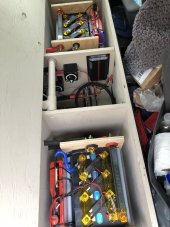
There are two rods evenly spaced on the bottom, you can’t really see the closest one.
 
Hi!

Is this for stationery application or mobile?
Because if mobile, given the cell's weight, I believe rubbing due to vibration could lead to PEX's failure
Mobile, these cells don’t move at all under 640 psi of compression.
 

Attachments

  • 2F6B5B2C-712E-49D7-A6E0-889C35ABC8B0.jpeg
    2F6B5B2C-712E-49D7-A6E0-889C35ABC8B0.jpeg
    169.1 KB · Views: 34

diy solar

diy solar
Back
Top