diy solar

diy solar

Daly bms make communication with Victron energy via interface board

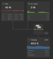
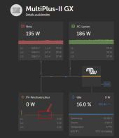
Ok, it runs now for some days and it looks good now, only really bad Weather now, today snow, so not much Energy from the Sky:
1673783960475.png

I ordered now an ET340 for the GoodWe Inverter to show them up in the overview. I set the EM42 to Address #2, I assume the ET340 will be on Address #1. Then I can put them both on the same USB-RS485 Adapter. Right?
 
Hi,

I need to connect 3 WNT boards together using CAN. is there any setting i must set so that the 3 boards can talk to each other?
regards
 
Hi,

I need to connect 3 WNT boards together using CAN. is there any setting i must set so that the 3 boards can talk to each other?
regards
As far as my experience is, you first have to assemble all 3 battery packs, each with its own BMS and interface board.
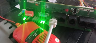
Then you need to set the ID of the interface boards to #0 (all DIP's down) and connect it to PC with an USB-RS485 (RJ45 jacket) Cable.
Then take this BMS Monitor Software to connect to each of the interface boards and set the protocol of your Inverter.
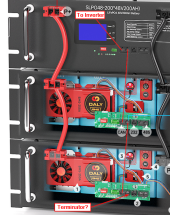
Then you have to set each board to an different ID with the DIP's. After that you have to connect them together as daisy chain, on the last port maybe an terminator, not sure, for single board not needed:
1673963881673.png
In the Inverter you have to set up the CAN to Other BMS 500kbit. Then all three boards should show up in your inverter.
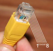
But be sure that all the cables are correct:
1673964150363.png
DALY INTERFACE BOARD Side:
3 - GND (green/white)
4 - CAN-L (blue)
5 - CAN-H (blue/white)

For example, Victron VE.CAN Side:
3 - GND (Green/white)
8 - CAN-L (Brown)
7 - CAN-H (Brown/white)

I hope that helps.
Greetings Jack
 
When the CAN is the host, use the 485 for parallel..
When the 485 is the host, use the CAN for parallel..

DIP switch
#1- 1 up rest is down
#2- down-up- rest is down
#3- 2 up and rest down
You don’t have to do the address on pc,
setting the dip switch will give them address automatically.
 
Last edited:
Hello again, now my system is running for a while, seems ok, except of absence of the sun... :(
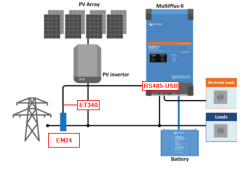
I have only one thing left, where I'm not sure if this is ok or not: I have two Energy meters, EM24 for the Grid Measurement and an ET340 for the GoodWe Inverter:
1674631702439.png
Both are connected parallel to one RS485-USB Cable.
It seems to work fine, but sometimes I have gaps in the measurement of the Inverter:
1674631797527.png
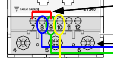
I connected them as they should be:
EM24:1674632059871.png ET340:1674632221386.png

But I was unsure about that red termination bridge on the ET340 and as Victron said nothing about it on the installation page so I kept it away.
But in the Manual of the RS485-USB Cable there are some information about the 120R Terminating Resistor: Only Required if the USB-RS485-WE cable is the first or last device in a multi-drop RS485 System, to meet RS485 Termination Requirements.

So what should I do? Add only the Bridge or connect somehow the terminator Pins 4 and 6 of the Cable?
Thanks a lot for help!
 
Hello again, now my system is running for a while, seems ok, except of absence of the sun... :(
I have only one thing left, where I'm not sure if this is ok or not: I have two Energy meters, EM24 for the Grid Measurement and an ET340 for the GoodWe Inverter:
View attachment 131412
Both are connected parallel to one RS485-USB Cable.
It seems to work fine, but sometimes I have gaps in the measurement of the Inverter:
View attachment 131413
I connected them as they should be:
EM24:View attachment 131414 ET340:View attachment 131415

But I was unsure about that red termination bridge on the ET340 and as Victron said nothing about it on the installation page so I kept it away.
But in the Manual of the RS485-USB Cable there are some information about the 120R Terminating Resistor: Only Required if the USB-RS485-WE cable is the first or last device in a multi-drop RS485 System, to meet RS485 Termination Requirements.

So what should I do? Add only the Bridge or connect somehow the terminator Pins 4 and 6 of the Cable?
Thanks a lot for help!

The first thing I need to understand is, are you connected to Victron's 485? This protocol is not written in my base version program
 
Hello again, now my system is running for a while, seems ok, except of absence of the sun... :(
I have only one thing left, where I'm not sure if this is ok or not: I have two Energy meters, EM24 for the Grid Measurement and an ET340 for the GoodWe Inverter:
View attachment 131412
Both are connected parallel to one RS485-USB Cable.
It seems to work fine, but sometimes I have gaps in the measurement of the Inverter:
View attachment 131413
I connected them as they should be:
EM24:View attachment 131414 ET340:View attachment 131415

But I was unsure about that red termination bridge on the ET340 and as Victron said nothing about it on the installation page so I kept it away.
But in the Manual of the RS485-USB Cable there are some information about the 120R Terminating Resistor: Only Required if the USB-RS485-WE cable is the first or last device in a multi-drop RS485 System, to meet RS485 Termination Requirements.

So what should I do? Add only the Bridge or connect somehow the terminator Pins 4 and 6 of the Cable?
Thanks a lot for help!
try only make connection with pin 4 ande pin6
 
The first thing I need to understand is, are you connected to Victron's 485? This protocol is not written in my base version program
No, I'm not. Only the Meters are connected to USB through an 5m RS485-USB Cable, that what Victron prefer. And the BMS is connected via CAN.
try only make connection with pin 4 ande pin6
Pin 4+6 of the Cable is the 120R Resistor, but where to connect it to? To which of the two meter and which pins?
 
No, I'm not. Only the Meters are connected to USB through an 5m RS485-USB Cable, that what Victron prefer. And the BMS is connected via CAN.

Pin 4+6 of the Cable is the 120R Resistor, but where to connect it to? To which of the two meter and which pins?
Sorry we dont write any rs485 protocol for victron ,only VEcanbus
 
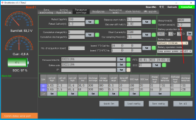
Where can I get the lcd display that is in the above picture for this new Daly server rack set up? also the smart active balencer. Is there going to be any future software that uses the rs485 port so the bms can control it directly by connecting it to bms? Also can the active balencer be used in parallel for 2 amps by using the rs485 port
 
Hello.
After reading all discussion, maybe someone can help me.
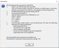
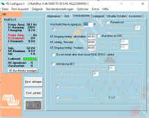
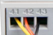
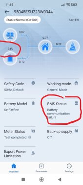
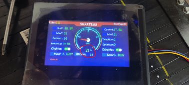
Tried to connect my home made battery with all Daly boards, but cant connect Goodwe GW5048D-ES with BMS, dont read anything.
Can someone give me an help?
I dont undertstand anything about protocols or eletronics, only know about building this kind of things ;)

1684151836174.jpg1684151836189.jpg1684151836182.jpg
 
Think were in the same situation , trying to get a bms to talk to victron , have you got an active balancer that may help
 
All the Daly Accessories you can buy here: https://www.aliexpress.com/item/1005005234080787.html
The software for PC, to connect to the RS485 Port, you can download here under Resources.
You can add the active Balancer in parallel, they just work independent.
Thanks for that , your doing exactly what i want to achieve . If you have the time can u explain how i get a victron mppt rs 450 100 to talk to the daily bms ? have i missed something in the last conversation
 
Back
Top