diy solar

diy solar

Daly bms make communication with Victron energy via interface board

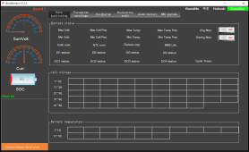
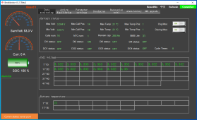
I finally got my Daly smart bms, with daly interface board and daly parallel module to communicate with my 12K GSL Hybrid inverter using pylon protocol… i have 3 battery bank with different AH capacity 1st is 280 ah, 2nd is 300ah and 3rd is 160ah… I believe the daly interface board and parallel module is doing a great job keeping them balanced with almost same percentage.
View attachment 128280
View attachment 128275
During Charging:
View attachment 128278
During: Discharging
View attachment 128279
Such great JOB,you made it
Now i m developing a 48V 100A/120A BMS of daly solar bms , Integrated interface board and parallel module 10A on one pcba board
 
this is the message that shows up
use UART or Canbus to make upgrade in PC software,sorry that the Bluetooth problem of app made from our app supplier
now you could provide me your version of bms ,and i could solve it via Bluetooth also, cause now i have upgrade S19 file in the website
 
I am very sorry for the Bluetooth problems before, but this can be solved, just need you to provide me with your software version number and bms device function version, and I will provide bms upgrade firmware code for everyone to upgrade
 
Looks great! But you are not using Victron Inverter, right? You are using RS485 to communicate with the Inverter...
Was it necessary to program the interface boards (WNT)?
Victron canbus only ,now you make canbus communication okay?
 
Looks great! But you are not using Victron Inverter, right? You are using RS485 to communicate with the Inverter...
Was it necessary to program the interface boards (WNT)?
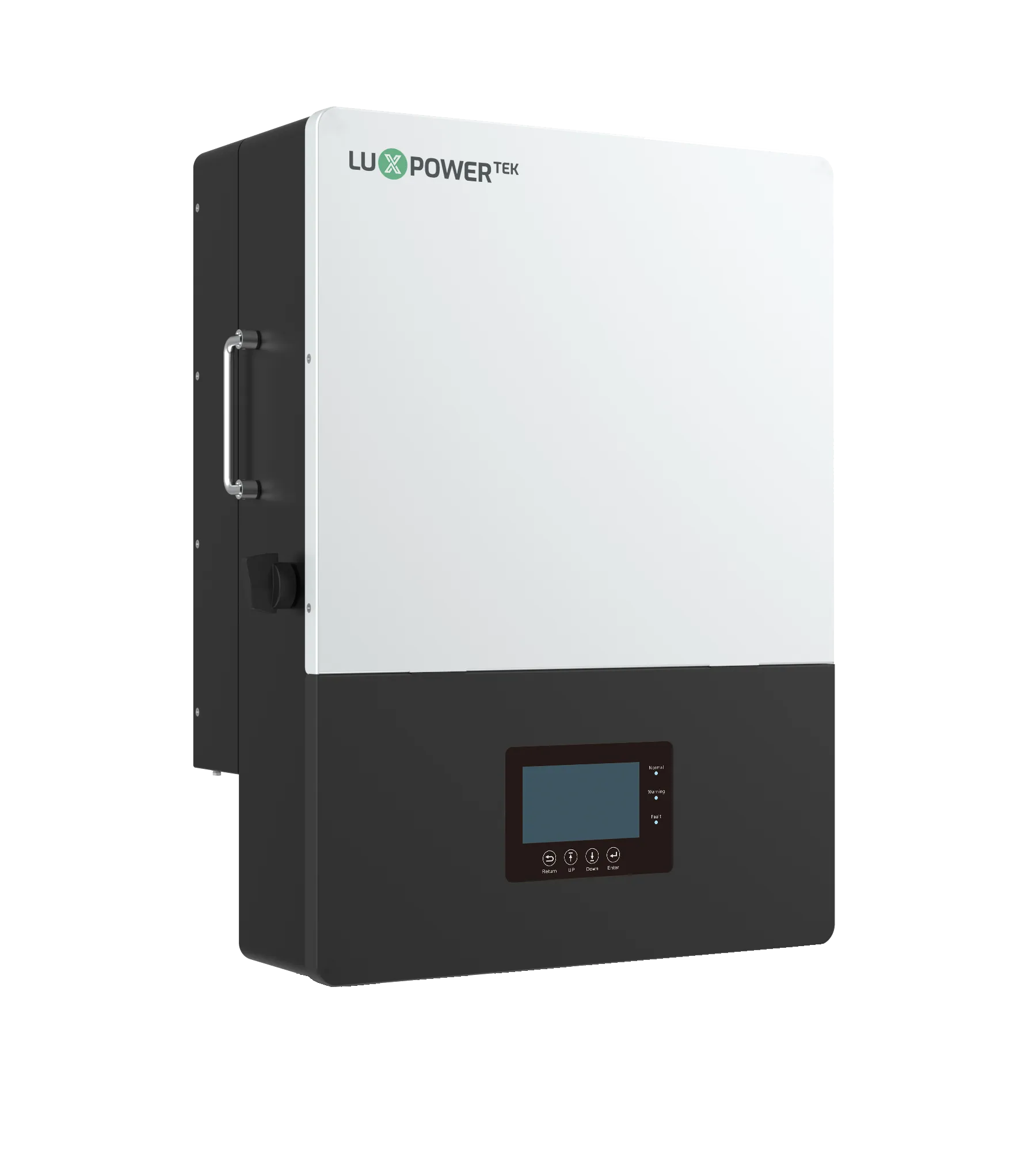
no I’m using the new GSL/LuxPower 12k hybrid inverter.
Communicating with thru CAN PYLON PROTOCOL.
Seller usually asked what kind inverter you have and they will program it for you.
if not you can Do it through their Pc software
 
use UART or Canbus to make upgrade in PC software,sorry that the Bluetooth problem of app made from our app supplier
now you could provide me your version of bms ,and i could solve it via Bluetooth also, cause now i have upgrade S19 file in the website
i have successfully using UART to make upgrades in PC software.
Dalys support said if you don’t have custom bms you shouldn’t do any upgrade with the bms.
 
I'm trying, but the Daly Support makes not easy for me. I have no idea how to program the Victron Can Protocol. They communicate together, but they don't recognize each other... :(
Check this out
 
Such great JOB,you made it
Now i m developing a 48V 100A/120A BMS of daly solar bms , Integrated interface board and parallel module 10A on one pcba board
Thanks. It’s much easier now that I can set the inverter to charge/discharge between 10-90% of my batter.
5A module should be enough.
 
Check this out
That one is from me ;-)
Does not work. I set the protocol, but no change.
 
That one is from me ;-)
Does not work. I set the protocol, but no change.
Make sure you restart the bms after you press select, press multiple time of the restart bms. wait 30secs and press read. To confirm it program it to the interface board.
 
Make sure you restart the bms after you press select, press multiple time of the restart bms. wait 30secs and press read. To confirm it program it to the interface board.
Interface Board or BMS? When I connect to the interface board, the program says connected, but no values are shown...
 
I don’t think its a Deye inverter, https://www.gsl-energy.com/usa-vers...d-solar-hybrid-power-inverter-mppt-controller , the interface board is partially working only when the battery is charging, but when on discharging it gives me a Bat fault…

That GSL is the re-branded LuxPower inverter:
 
Interface Board or BMS? When I connect to the interface board, the program says connected, but no values are shown...
What do you mean no valu? Can you take pictures or make video. Make sure you are connected to the right COM on your compute..
 
Interface Board or BMS? When I connect to the interface board, the program says connected, but no values are shown...
emm,your WNT version could you let me check, maybe its not the version have Victron, or your Pin defination connect its not correct
 
What do you mean no valu? Can you take pictures or make video. Make sure you are connected to the right COM on your compute..
Like that, no matter which version of the software I use:
1673248885662.png
I'm connected through the USB-RS485 (RJ45 Connector) with the WNT Board. The Drivers are installed well and working, right COM-Port, I have only one.

emm,your WNT version could you let me check, maybe its not the version have Victron, or your Pin defination connect its not correct
What version do you mean? Where can I see it?
When I oredered the Interface Board, they asked me for what Inverter and I told them for Victron CAN. That is also printed on the paper what was with the Board. I also created costom Connecton Cable, that they can communicate correctly:
---
VE.CAN Side <-> DALY INTERFACE BOARD SIDE
Green/white GND 3 - 3 GND green/white
Brown CAN-L 8 - 4 CAN-L blue
Brown/white CAN-H 7 - 5 CAN-H blue/white
---
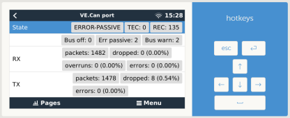
Communication seems to work fine:
1673249297782.png
But no BMS is visible in the Devices or Battery Monitor List....
 
Make sure all the dip switch switches are in down position
That did it! (y)

Now I could read out the inverter settings and you won't believe, they set VOLTRONICS+CAN, not VICTRON+CAN.... ?‍♂️
1673290467736.png

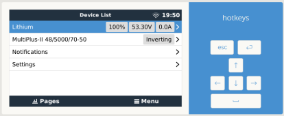
I set now VICTRON+CAN and voila, it is visible in the device List!
1673290241682.png

Now I have only one problem, the Victron runs directly from the Battery and is consumpting ~37W/-0.7A in Inverter Mode, but in the software or in the BMS directly, over BT, it shows 0.0A current. Only if the consumption goes over ~2.5A, the BMS shows it, below it shows always 0.0A, when I look internal Battery Monitor of the MP2, it shows me correctly ~37W/-0.7A.
Is this normal?

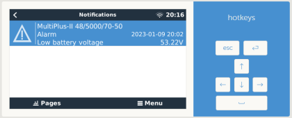
And for some reason I get suddently get now the error:
1673291792117.png
And the ESS is now off, any idea why? In the BMS are all Alarms on ok and 53.22V is not really low...
 
Last edited:
That did it! (y)

Now I could read out the inverter settings and you won't believe, they set VOLTRONICS+CAN, not VICTRON+CAN.... ?‍♂️
View attachment 128747

I set now VICTRON+CAN and voila, it is visible in the device List!
View attachment 128745

Now I have only one problem, the Victron runs directly from the Battery and is consumpting ~37W/-0.7A in Inverter Mode, but in the software or in the BMS directly, over BT, it shows 0.0A current. Only if the consumption goes over ~2.5A, the BMS shows it, below it shows always 0.0A, when I look internal Battery Monitor of the MP2, it shows me correctly ~37W/-0.7A.
Is this normal.
Very nice you got in…
Now if you want you bms to show A reading below 2.5A. Go under parameters on the pc and change the Current Wave(A) to 0.2…
 
Back
Top