


You are using an out of date browser. It may not display this or other websites correctly.
You should upgrade or use an alternative browser.
You should upgrade or use an alternative browser.
JK BMS CAN bus comms now possible for inverters that support Goodwe and Pylontech batteries
- Thread starter uksa007
- Start date
uksa007
Solar Enthusiast
- Joined
- May 26, 2022
- Messages
- 239
Hardware interface currently in final stages of testing, limited number available, register your interest at Patreon
Provides all the hardware needed to connect the JK-BMS to Inverter
Fully tested Plug and Play, connect to JK-BMS with the supplied 4 pin cable, plug in RJ45 Inverter cable and supply power with the supplied USB cable.
Kit will consist of:

Provides all the hardware needed to connect the JK-BMS to Inverter
Fully tested Plug and Play, connect to JK-BMS with the supplied 4 pin cable, plug in RJ45 Inverter cable and supply power with the supplied USB cable.
Kit will consist of:
- ESP32 Development board
- Latest Firmware installed with:
- Captive portal AP to connect to existing WiFi network
- Standalone AP mode
- Web server for standalone management
- Home Assistant integration
- CAN interface PCB board with:
- CAN bus transceiver high quality Texas Instruments native 3.3v
- CAN bus termination selectable with solder jumper, on by default.
- RJ45 CAN bus connector for Inverter, standard wiring for direct inverter connection pin 4H, 5L
- JK-BMS 4 pin interface connector
- JK-BMS 4 pin cable supplied
- USB Cable supplied for power and data
Hello, I have bought a ESP32 Wroom, a DC-DC conversion module (to pull power from the JK switch/screen port), RS485 -> TTL converter, TTL -> CAN converter TJA1050.
Can you confirm pinout ?
From JK BMS with RS485 module Yellow -> A+, White B- and from the RS485 transceiver TX -> ESP32 pin 17, RX -> ESP32 pin 16 and then from ESP32 to TJA1050 ESP32 pin 14 -> TJA1050 TX and ESP32 pin 4 -> 4.7kohm -> TJA1050 RX ?
Is this all ok ?
Or maybe for 1 meter of cable lenght I can connect the JK directly to ESP32 ? Which color goes where ? Yellow -> TX or yellow -> RX ?
Thank you")
Can you confirm pinout ?
From JK BMS with RS485 module Yellow -> A+, White B- and from the RS485 transceiver TX -> ESP32 pin 17, RX -> ESP32 pin 16 and then from ESP32 to TJA1050 ESP32 pin 14 -> TJA1050 TX and ESP32 pin 4 -> 4.7kohm -> TJA1050 RX ?
Is this all ok ?
Or maybe for 1 meter of cable lenght I can connect the JK directly to ESP32 ? Which color goes where ? Yellow -> TX or yellow -> RX ?
Thank you
Last edited:
uksa007
Solar Enthusiast
- Joined
- May 26, 2022
- Messages
- 239
Hi,Hello, I have bought a ESP32 Wroom, a DC-DC conversion module (to pull power from the JK switch/screen port), RS485 -> TTL converter, TTL -> CAN converter TJA1050.
Can you confirm pinout ?
From JK BMS with RS485 module Yellow -> A+, White B- and from the RS485 transceiver TX -> ESP32 pin 17, RX -> ESP32 pin 16 and then from ESP32 to TJA1050 ESP32 pin 14 -> TJA1050 TX and ESP32 pin 4 -> 4.7kohm -> TJA1050 RX ?
Is this all ok ?
Or maybe for 1 meter of cable lenght I can connect the JK directly to ESP32 ? Which color goes where ? Yellow -> TX or yellow -> RX ?
Thank you
The BMS side looks correct, please see here for more info https://github.com/Uksa007/esphome-jk-bms-can#schematics
1m for the TLL cable is probably getting a bit long I would recommend keeping it under 30cm or use the RS485 modules.
The TJA1050 I normally use:
can_tx_pin: GPIO23
can_rx_pin: GPIO22
Regards.
TahitiKnx
New Member
Exciting Announcement.
I Have been busy designing a hardware Plug and play hardware interface to make connection to the BMS plug and play.
Will be available to Patreon members first
Hello, does it help to connect different can protocols eachother for example a can 2.0B inverter to another can protocole battery of third party brand thru RJ45 cable ? i am looking for can protocole is for alpha ESS smile 5 batt and need to know what pin are for CAN H and Can L in order to connect to a sofar solar inverteur. can you help ? Facebook Good Wize from French Polynesia
Hi on my sofar me3000sp pin 4 is can H and pin 5 is can L.Hello, does it help to connect different can protocols eachother for example a can 2.0B inverter to another can protocole battery of third party brand thru RJ45 cable ? i am looking for can protocole is for alpha ESS smile 5 batt and need to know what pin are for CAN H and Can L in order to connect to a sofar solar inverteur. can you help ? Facebook Good Wize from French Polynesia
uksa007
Solar Enthusiast
- Joined
- May 26, 2022
- Messages
- 239
Hi,Hello, does it help to connect different can protocols eachother for example a can 2.0B inverter to another can protocole battery of third party brand thru RJ45 cable ? i am looking for can protocole is for alpha ESS smile 5 batt and need to know what pin are for CAN H and Can L in order to connect to a sofar solar inverteur. can you help ? Facebook Good Wize from French Polynesia
Not really following why you need CAN 2.0B eg 29 bit identifiers?
Alpha is normally CAN using the pylon protocol eg CAN 2.0A 11 bit identifiers, as do most inverters.
The normal pins for RJ45 CAN are Pin 4 H, Pin 5 L
uksa007
Solar Enthusiast
- Joined
- May 26, 2022
- Messages
- 239
Hi,Hi on my sofar me3000sp pin 4 is can H and pin 5 is can L.
Is your Sofar solar inverter working well using my code eg CAN Goodwe/Pylon?
I should probably start to put a list together of confirmed working inverters.
Can you let me know how you configured the inverter to work correctly?
Thanks.
Last edited:
Hi yes it works well. I connect via the can port on inverter and select general lithium in the battery parameters. The only issue i have is with the absorption, when I charge it only shows bulk upto 100% and then will stop charging and dosnt absorb. It will balance the cells as they hit 3.45v but then won't absorb. Not sure if my absorption voltage should be set higher or lower. Currently set to 55.2v (which I believe is the voltage you put in the script). Other than that though it works perfect. Thank you for all your effort.Hi,
Is your Sofar solar inverter working well using my code eg CAN Goodwe/Pylon?
I should probably start to put a list together of confirmed working inverters.
Can you let me know how you configured the inverter to work correctly?
Thanks.
uksa007
Solar Enthusiast
- Joined
- May 26, 2022
- Messages
- 239
Does the Battery Voltage ever reach 55.2V?Hi yes it works well. I connect via the can port on inverter and select general lithium in the battery parameters. The only issue i have is with the absorption, when I charge it only shows bulk upto 100% and then will stop charging and dosnt absorb. It will balance the cells as they hit 3.45v but then won't absorb. Not sure if my absorption voltage should be set higher or lower. Currently set to 55.2v (which I believe is the voltage you put in the script). Other than that though it works perfect. Thank you for all your effort.
Once it reaches 100% what is the Charging Status in the ESP32 logs or Home Assistant.
Thinking the inverter may not show Absorption, after the battery reaches 55.2V is should stay there for 30min (absorption)
Last edited:
TahitiKnx
New Member
Thank you, when i connect a sofarsolar inverter with its cable to a n Alpha Ess Battery, the batterie is not recognised.Hi,
Not really following why you need CAN 2.0B eg 29 bit identifiers?
Alpha is normally CAN using the pylon protocol eg CAN 2.0A 11 bit identifiers, as do most inverters.
The normal pins for RJ45 CAN are Pin 4 H, Pin 5 L
uksa007
Solar Enthusiast
- Joined
- May 26, 2022
- Messages
- 239
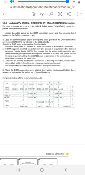
Edit confirmed from another source this is what you need:Thank you, when i connect a sofarsolar inverter with its cable to a n Alpha Ess Battery, the batterie is not recognised.
Alpha ESS SMILE5-BAT Quick Installation Manual page 6
Suggests the following, should be similar for your inverter

On means switch UP, DIP 2 and 3 ON labels are wrong.
Last edited:
TahitiKnx
New Member
Hi, now can H and can L are connected from battery to inverter but inverter dont recognise battery. i notice that amass smile 5 batteri wait for un ground on one rj45 pin and my inverter dont provide any ground thru rj10-rj45 pinsThank you, when i connect a sofarsolar inverter with its cable to a n Alpha Ess Battery, the batterie is not recognised.
uksa007
Solar Enthusiast
- Joined
- May 26, 2022
- Messages
- 239
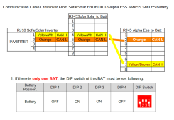
Did you wire it as above (2-5 and 7-4) and set the correct dip switches?Hi, now can H and can L are connected from battery to inverter but inverter dont recognise battery. i notice that amass smile 5 batteri wait for un ground on one rj45 pin and my inverter dont provide any ground thru rj10-rj45 pins
CAN does not require a GND it is a differential pair.
TahitiKnx
New Member
ohwww you mean alpha Ess CAN H and Can L are not pin 4 and pin 5 but oin 7 and pin 2 ? if that correct i have to re swapp pins. i dont have anymore pluggs, have to wait tuesday.Edit confirmed from another source this is what you need:
Alpha ESS SMILE5-BAT Quick Installation Manual page 6
Suggests the following, should be similar for your inverter
View attachment 143876
On means switch UP, DIP 2 and 3 ON labels are wrong.
now dip 2 and 3 are on and dip 1 and 4 offpower DV from batt to inverter not connected yet. bad cable.
can you prive this alpha ess manual with can h can l to 2 and 7 pin and dont have that one please
Last edited:
TahitiKnx
New Member
yes tks correct for me tooHi on my sofar me3000sp pin 4 is can H and pin 5 is can L.
uksa007
Solar Enthusiast
- Joined
- May 26, 2022
- Messages
- 239
Yes you need to swap Alpha seem to use 7 and 2 with the dip switches 2 and 3 ON!ohwww you mean alpha Ess CAN H and Can L are not pin 4 and pin 5 but oin 7 and pin 2 ? if that correct i have to re swapp
TahitiKnx
New Member
Tks it's now in my side to act, just to find to make correct cable and pluggsYes you need to swap Alpha seem to use 7 and 2 with the dip switches 2 and 3 ON!
TahitiKnx
New Member
Edit confirmed from another source this is what you need:
Alpha ESS SMILE5-BAT Quick Installation Manual page 6
Suggests the following, should be similar for your inverter
View attachment 143876
On means switch UP, DIP 2 and 3 ON labels are wrong.
Attachments
TahitiKnx
New Member
That's what I posted already.
Does it work?
Last edited:
Thanks, I will post report once I have received everything.Hi,
The BMS side looks correct, please see here for more info https://github.com/Uksa007/esphome-jk-bms-can#schematics
1m for the TLL cable is probably getting a bit long I would recommend keeping it under 30cm or use the RS485 modules.
The TJA1050 I normally use:
can_tx_pin: GPIO23
can_rx_pin: GPIO22
Regards.
TahitiKnx
New Member
Hi Uksa007, i have now connected wire as above (2-5 and 7-4) and set the correct dip switches 2 and 3 ON; Battery is not seen on SofarSolar graphic on inverter panel. i tested DC outlet from inverter 3.5V; then connected DC power cable and i have 56,7V, those volts come from battery but inverter is not charging battery; Event list : ID52 BMS disconnected and ID 36 Meter com Fault
Last edited:
Similar threads
- Replies
- 1K
- Views
- 42K
- Replies
- 47
- Views
- 9K
- Replies
- 27
- Views
- 859
- Replies
- 2
- Views
- 454
- Replies
- 9
- Views
- 674