


You are using an out of date browser. It may not display this or other websites correctly.
You should upgrade or use an alternative browser.
You should upgrade or use an alternative browser.
Second battery bank questions!
- Thread starter JonL
- Start date
A few other tips for rookies like me. Every time you unhook your battery bank, and do some work, it seems you have to let the batteries equalize again, as mine had big divergence from battery the battery.
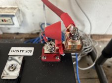
Also, when connecting a resistor to your bus bar, make sure it’s on the main part of the bus bar not touching a screw. Otherwise you get big Sparks!
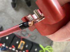
And when hooking up the on/off switch to the battery bank, you have to crimp one part of the copper lug to the opposite direction, so it will fit properly. Picture enclosed. ?
Also, when connecting a resistor to your bus bar, make sure it’s on the main part of the bus bar not touching a screw. Otherwise you get big Sparks!
And when hooking up the on/off switch to the battery bank, you have to crimp one part of the copper lug to the opposite direction, so it will fit properly. Picture enclosed. ?
Attachments
Just realized that they’re not the real problem, just how I was handling them. The way to avoid problems are some of the points noted in my last post. The real fix is to not connect the final wire until the switch is on and then using a resister to make the final attachment. And you can turn them on and off with no problems, just like with the inverter. I’m self taught, which means a hard and sometimes long learning curve!?I applaud you for continuing to use those switches even when multiple people are telling you they are wrong for your system.
TomC4306
Solar Obsessive
You didn't look very hardDo you know what the torque is for SOK? On most of the equipment, I could never find this kind of information. ?
Update: very little change in the wide gap of charging and discharging between the battery banks. If anybody has any suggestions that they might find later on, please post them here.
One thing I would say, would be not to use Battle Born Batteries and SOK together, doesn’t seem like a good match! ?
One thing I would say, would be not to use Battle Born Batteries and SOK together, doesn’t seem like a good match! ?
Sorry, I’ve been too busy trying to get my system up and running again. I don’t think the tightening of bolts is going to make that much difference.You didn't look very hard
I use an infrared thermometer to check all possibility of heat problems.
It’s going to take me a while to learn how to use the equipment for tightening bolts, and nuts. ?
Can you summarize the state of the system? I'm particularly interested to know how the solar charge controllers are networked with the shunt(s).
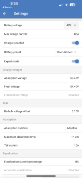
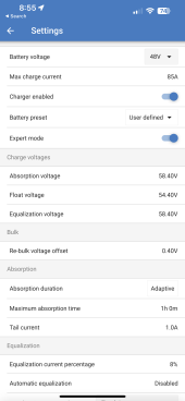
The charge controllers parameters are set by VictronConnect app on my phone. I’m using the same settings for both batteries.Can you summarize the state of the system? I'm particularly interested to know how the solar charge controllers are networked with the shunt(s).
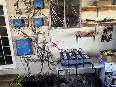
With the Victron energy VE bus, smart dongle wire is connected to the inverter. I thought about getting another one of these, and connect it to the inverter, but I have no clue if that would change anything?
In the picture here is the latest configuration. ?
Attachments
You have two shunts. Which shunt are the solar charge controllers networked with?
Below are screenshots from the demo library of VictronConnect. When looking at your shunt, click on the Gear icon (configuration) and you'll get the menu in the left screenshot. Click on the circled item and you'll get the second screen.

Both shunts are on the same network!You have two shunts. Which shunt are the solar charge controllers networked with?
Attachments
I was talking to somebody from Victron on one of the YouTube channels, he states that you can change the charging settings differently for each battery bank, using the Victron shunt!
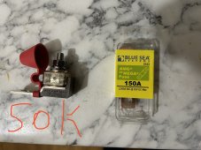
Also, I’m wondering if perhaps the different types of fuses are causing the SOK battery bank more resistance? Below is the photograph, the one fuse on the left is the one I’m using for SOK and the one on the right is for battleborn. In the picture it shows 300 A, but it’s actually 150 on the SOK.
Also, I’m wondering if perhaps the different types of fuses are causing the SOK battery bank more resistance? Below is the photograph, the one fuse on the left is the one I’m using for SOK and the one on the right is for battleborn. In the picture it shows 300 A, but it’s actually 150 on the SOK.
Attachments
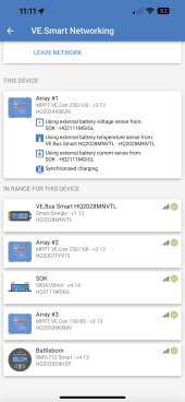
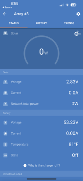
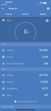
Your screenshot shows three arrays but only one shunt. The Array #1 MPPT is using the current and voltage from the SOK shunt, but the temperature from the VE Bus Smart. That seems odd. Why isn't it picking up the temperature from the SOK shunt?
I think a screenshot from each of the three MPPT's networking screen would be helpful.
I'm going to throw out my theory here so anyone can pick it apart. The caveat here is that while I have a Victron shunt and use it in a network with two Victron MPPT devices and two 4s 280 Ah batteries, I haven't played around with the networking much
1. A shunt, by itself, does not limit charge or discharge
2. The shunts are reporting the voltage and current of each battery bank
3. Both batteries and shunts are attached to the same common bus bars
4. A solar charge controller that thinks it is charging the SOK battery bank, is also charging the Battleborn battery bank and vice-versa.
With regard to your question about fuses, I would be more concerned if you were using different types of fuses (Class T vs MRBF) or different brands.
I think because the VE Bus smart has has a temp probe built in, you have to add a temp prob to the start shunt for it to report back.Your screenshot shows three arrays but only one shunt. The Array #1 MPPT is using the current and voltage from the SOK shunt, but the temperature from the VE Bus Smart. That seems odd. Why isn't it picking up the temperature from the SOK shunt?
I think a screenshot from each of the three MPPT's networking screen would be helpful.
I'm going to throw out my theory here so anyone can pick it apart. The caveat here is that while I have a Victron shunt and use it in a network with two Victron MPPT devices and two 4s 280 Ah batteries, I haven't played around with the networking much
1. A shunt, by itself, does not limit charge or discharge
2. The shunts are reporting the voltage and current of each battery bank
3. Both batteries and shunts are attached to the same common bus bars
4. A solar charge controller that thinks it is charging the SOK battery bank, is also charging the Battleborn battery bank and vice-versa.
With regard to your question about fuses, I would be more concerned if you were using different types of fuses (Class T vs MRBF) or different brands.
I do agree think changing any voltage setting on a smart shunt will just adjust the % readings and if linked to a SCC will report the voltage to the SCC vs the SCC terminal voltage as a controlling voltage.
A couple screen shots back you have current draw of both shunts reporting and the SOK was substantially lower.
There are two shunts, one off the SOK batteries and one off of the Battle Born Batteries. The Battle Born Batteries has the VE dongle that would report the temperature. SOK has none.Your screenshot shows three arrays but only one shunt. The Array #1 MPPT is using the current and voltage from the SOK shunt, but the temperature from the VE Bus Smart. That seems odd. Why isn't it picking up the temperature from the SOK shunt?
I think a screenshot from each of the three MPPT's networking screen would be helpful.
I'm going to throw out my theory here so anyone can pick it apart. The caveat here is that while I have a Victron shunt and use it in a network with two Victron MPPT devices and two 4s 280 Ah batteries, I haven't played around with the networking much
1. A shunt, by itself, does not limit charge or discharge
2. The shunts are reporting the voltage and current of each battery bank
3. Both batteries and shunts are attached to the same common bus bars
4. A solar charge controller that thinks it is charging the SOK battery bank, is also charging the Battleborn battery bank and vice-versa.
With regard to your question about fuses, I would be more concerned if you were using different types of fuses (Class T vs MRBF) or different brands.
The temperature shows up in the VictronConnect app. On the charge controllers & the inverter. The SOK batteries don’t show a temperature, so I’m likely to have to get another dongle or some other temperature measuring device. ?
Attachments


Can you give me what the acronym of SCC is? ?I think because the VE Bus smart has has a temp probe built in, you have to add a temp prob to the start shunt for it to report back.
I do agree think changing any voltage setting on a smart shunt will just adjust the % readings and if linked to a SCC will report the voltage to the SCC vs the SCC terminal voltage as a controlling voltage.
A couple screen shots back you have current draw of both shunts reporting and the SOK was substantially lower.
I’ll try and change the fuse on the SOK batteries Sat, as it’s the first time I’ve tried this kind of fuse. That way I can find out whether it’s part of the problem or not. And I really don’t know if fuses have different resistance factors! ?
Adding to my theory list...
5. You have the potential to apply too many charging amps.
The three Victron solar charge controllers can together charge at a rate of 255 amps. All three are configured for a maximum of 85 amps, even though two of them could do 100 amps. As a whole, the three 48 volt batteries cannot handle this. Each string of Battleborn 100 amp batteries should be charged at no more than .5C or 50 amps per the Battleborn Data Sheet. The single string of SOK 100 amp batteries also should be charged at no more than .5C or 50 amps per the SOK web site. Therefore, the three batteries at a whole want no more than 150 amps, and it would be optimistic to assume that a 150 amp charge would be evenly split between the three batteries. Should the Battleborn batteries hit 100% state of charge and the BMS trip the high voltage disconnect, there is the potential to hit the SOK battery with three times the acceptable amps.
The way you have your Victron solar charge controllers setup, one or two of them will cut off charging if the shunt they are connected to tells them the battery is full. But one or two of the other solar charge controllers are going to keep cranking because the shunt they are connected to says that its battery is not full. So what happens is that all three battery banks are going to continue to receive a charge until all three batteries are full.
I have two Victron MPPT 100/50 solar charge controllers in my system. So a maximum of 100 amps. That maximum is well under the maximum that either of my two 280 Ah batteries, and their BMS, can accept individually. What this means is that should one battery reach 100% state of charge and trip the high voltage disconnect, it's OK for the other battery to take on the whole 100 amps of charge current. Your system probably can't do that.
Similar threads
- Replies
- 16
- Views
- 347
- Replies
- 2
- Views
- 171
- Replies
- 7
- Views
- 248
- Replies
- 4
- Views
- 198