diy solar

diy solar

Replacing FANS inside the EG4 6500EX-48 to make it quiet

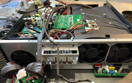
I got a couple of these wired and soldered up today but probably won't get a chance to install them until this weekend.

View attachment 148721

I've taken some preliminary decibel level readings at key times throughout the day so I'll have something to compare to after the install.

At base load of around 600W my inverters run between 40 and 43C. I think I'll try out the same settings you used. Minimum fan speed at 35C and maximum at 55C.
Perfect! I'm very curious about your temperature test results under inverter load and charging conditions (as I've already wrote, I'm still only able to do inverter idle temperature tests with this modding...). Also looking forward about the results of your decibel changes!
 
I got a couple of these wired and soldered up today but probably won't get a chance to install them until this weekend.

View attachment 148721

I've taken some preliminary decibel level readings at key times throughout the day so I'll have something to compare to after the install.

At base load of around 600W my inverters run between 40 and 43C. I think I'll try out the same settings you used. Minimum fan speed at 35C and maximum at 55C.
Hi ! Where did you source these controllers ? EBAY, im going to go ahead and order 3 as well, THANK YOU!

~RandomPlanet
 
I have two inverters in split phase. I installed the controllers in the L2 inverter today(not until after the batteries were fully charged, so minimal PV input) and wanted to share some initial findings.

Settings for all three controllers:
Po = min
Tu = 35C
Td = 20C

So far the L2 inverter has been running 3 to 5 degrees celsius warmer, but is significantly quieter. I am going to monitor the temps and play around with the settings on the controllers for a few days before installing them in the L1 inverter.


IMG_20230512_152326_758.jpg
 
I have two inverters in split phase. I installed the controllers in the L2 inverter today(not until after the batteries were fully charged, so minimal PV input) and wanted to share some initial findings.

Settings for all three controllers:
Po = min
Tu = 35C
Td = 20C

So far the L2 inverter has been running 3 to 5 degrees celsius warmer, but is significantly quieter. I am going to monitor the temps and play around with the settings on the controllers for a few days before installing them in the L1 inverter.


View attachment 148987
Cool! Looks exact like my modding :cool:

I'm curious how your test results will be with PV charging and inverter load. In the meantime I've got my AC-in connected from the electrician (still no AC-out connected to do inverter load tests and still no PV). So I was able to do battery charging tests with the modded fans. I have about 2-5 degree celsius more just with AC charging which is ok because it stays below 50 degree celsius with an ambient temperature of about 28 celsius while charging current is limited to 30A per EG4. Still nice silent compared to the original fan working mode.

When running the 4 modded EG4's I read about 59-60 dB and when adding the unmodded additional 2 inverters, it adds up to 70-71 dB.
 
Hi there!
I am trying to determine what type of "white" tape you guys are using to adhere your Controller boards to the plastic inside the inverter. I have my controllers ready.... Ive installed some Venting and some exhaust Fans in my "Power closet" as it gets quite warm in there
.... and will soon do the fan mod..... Any help identifying the tape is appreciated.

~RandomPlanet
I've used 3M VHB tape... it's like magic!

Btw. I've taped a dozen 100W PV panels with Z-brackets on my motorhome roof with this VHB tape - no roof penetration and stronger compared to screws (just in case and as a final safeguard I've secured them with a Stainless Steel Wire Rope 316 - but for now it's still rock solid after 1 year using in extreme heat conditions)!
 
Hello Friends;
I have NOT yet modded the EG4 6500 with my Temp Controlled fans yet ( to reduce noise)....
Mainly because I have a concern of the unit running too hot with the Stock configuration... It's running WAY too hot for my liking in a Large Closet (I know, I know) I need to have ambient temperature control...

So I have Installed Temperature controlled Intake and Exhaust fans to this room to try and keep the room manageable.
(AC Infinity AIRFRAME T7 White, High-Airflow Cooling Fan System 17")

I think my focus is slightly trending to Modding and/ or adding additional cooling Fans to the INVERTER itself for Thermal reasons more so than reducing noise at this point......
The last thing I want is to make things QUIET and then diminish the lifespan of the Inverter itself!!

I have searched UP and DOWN about flipping the fans over and converting the inverter to draw air through the bottom(Convection), and out the top...(Removing the filters at the top) ... and introducing filters at the fan intake??.... I cant seem to find a reason why this would NOT be effective..... Just to flip the fans over in the stock configuration and then remove the top filters. For reference: Here is an example of my concern:
Any ideas welcome ... Did anyone else move forward with the PWM 12v Temp Controllers to see if the inverter remains stable and cool ?

Thanks !

~RandomPlanet
 

Attachments

  • Screenshot 2023-05-31 at 3.15.00 PM.png
    Screenshot 2023-05-31 at 3.15.00 PM.png
    162.4 KB · Views: 27
  • Screenshot 2023-05-31 at 3.14.10 PM.png
    Screenshot 2023-05-31 at 3.14.10 PM.png
    75 KB · Views: 26
Hello Friends;
I have NOT yet modded the EG4 6500 with my Temp Controlled fans yet ( to reduce noise)....
Mainly because I have a concern of the unit running too hot with the Stock configuration... It's running WAY too hot for my liking in a Large Closet (I know, I know) I need to have ambient temperature control...

So I have Installed Temperature controlled Intake and Exhaust fans to this room to try and keep the room manageable.
(AC Infinity AIRFRAME T7 White, High-Airflow Cooling Fan System 17")

I think my focus is slightly trending to Modding and/ or adding additional cooling Fans to the INVERTER itself for Thermal reasons more so than reducing noise at this point......
The last thing I want is to make things QUIET and then diminish the lifespan of the Inverter itself!!

I have searched UP and DOWN about flipping the fans over and converting the inverter to draw air through the bottom(Convection), and out the top...(Removing the filters at the top) ... and introducing filters at the fan intake??.... I cant seem to find a reason why this would NOT be effective..... Just to flip the fans over in the stock configuration and then remove the top filters. For reference: Here is an example of my concern:
Any ideas welcome ... Did anyone else move forward with the PWM 12v Temp Controllers to see if the inverter remains stable and cool ?

Thanks !

~RandomPlanet
I know, it's not an easy task to keep them cool AND quiet. My PWM temp controller modding is working great on all 18 stock fans (6 inverters) - BUT without active cooling the garage (15' high RV with 10' high 2-car in one large space) to reduce the ambient temperature, the fans speed up to full speed very fast. As a result, my goal to make them quiet AND cool does not work without active cooling. But active cooling of the garage was planned anyway because it gets HOT in the Mohave desert (>120F) ?

Now I've decided to install a dual zone mini split system in my garage, one with a typical wall indoor unit to reduce the ambient (also good for the batteries) and one concealed indoor unit to just cool the inverters itself where I want to run duct to each of the inverters air intakes (on both upper sides of each inverter).

I hope, with these additional active cooling and the already implemented fan modding, I can keep the inverters cool AND quite!

Since a couple of days, my 3D printer is printing custom duct work adapter parts to direct the air to the exact locations where it is needed... :cool:
 
I really don't understand why it's engineered in this way to pull the air from the top to the bottom...

If it pulled air from the bottom, where would the air filters go? They would be behind the front bottom removable case, and you would have to remove the whole front bottom case including probably detaching the screen just to clean the air filters as suggested each month.


I have searched UP and DOWN about flipping the fans over and converting the inverter to draw air through the bottom(Convection), and out the top...(Removing the filters at the top) ... and introducing filters at the fan intake??.... I cant seem to find a reason why this would NOT be effective

The only reason this would be worse than the current configuration is what I mentioned above, you will have to remove the whole front bottom case, probably including the screen, in order to clean the filters each month as recommended.
 
I know, it's not an easy task to keep them cool AND quiet. My PWM temp controller modding is working great on all 18 stock fans (6 inverters) - BUT without active cooling the garage (15' high RV with 10' high 2-car in one large space) to reduce the ambient temperature, the fans speed up to full speed very fast. As a result, my goal to make them quiet AND cool does not work without active cooling. But active cooling of the garage was planned anyway because it gets HOT in the Mohave desert (>120F) ?

Now I've decided to install a dual zone mini split system in my garage, one with a typical wall indoor unit to reduce the ambient (also good for the batteries) and one concealed indoor unit to just cool the inverters itself where I want to run duct to each of the inverters air intakes (on both upper sides of each inverter).

I hope, with these additional active cooling and the already implemented fan modding, I can keep the inverters cool AND quite!

Since a couple of days, my 3D printer is printing custom duct work adapter parts to direct the air to the exact locations where it is needed... :cool:
WOW .. You have provided another GREAT Idea., @fmeili1 for the win again!
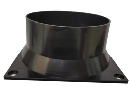
So what I am going to try is to 3d print a 4 inch duct adapter for my intake 120mm Fan(in Air conditioned room), and run duct(s) to the two Intake locations on the EG4.

The challenge will be to custom make a Filter Plate/Duct intake coupler . This way the EG4 will bring in Air conditioned air...
I thinik this might just work!

When you say you are 3d printing custom duct adapters, What exactly are you printing ?... are you indeed printing the adapter that attaches to the EG4 intake too ?.... if so , can you share your design / CAR file? Thanks in advance!..... Getting closer and closer..

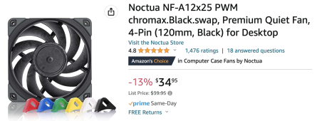
BTW: I bought two Noctua fans(NF-A12x25 PWM chromax.Black.swap) for the Intake vent to the closet .. These are EXTREMELY Quiet!

~RandomPlanet
 
If it pulled air from the bottom, where would the air filters go? They would be behind the front bottom removable case, and you would have to remove the whole front bottom case including probably detaching the screen just to clean the air filters as suggested each month.


The only reason this would be worse than the current configuration is what I mentioned above, you will have to remove the whole front bottom case, probably including the screen, in order to clean the filters each month as recommended.
You make fair points about the filters. I suppose it would be a terrible idea to NOT run filters. But what about custom fitting filters at the FANS themselves?.... Sure .. You are right about having to remove the bottom cage assembly...... a Bit of a pain.... but wonder how much cooler the unit would run..... maybe only a few degrees?

~RandomPlanet
 
If it pulled air from the bottom, where would the air filters go? They would be behind the front bottom removable case, and you would have to remove the whole front bottom case including probably detaching the screen just to clean the air filters as suggested each month.
You're right, with the current case design of the lower side of the inverter, it would be problematic to place the filters in a convenient and easy replaceable way.
 
WOW .. You have provided another GREAT Idea., @fmeili1 for the win again!
So what I am going to try is to 3d print a 4 inch duct adapter for my intake 120mm Fan(in Air conditioned room), and run duct(s) to the two Intake locations on the EG4.

The challenge will be to custom make a Filter Plate/Duct intake coupler . This way the EG4 will bring in Air conditioned air...
I thinik this might just work!

When you say you are 3d printing custom duct adapters, What exactly are you printing ?... are you indeed printing the adapter that attaches to the EG4 intake too ?.... if so , can you share your design / CAR file? Thanks in advance!..... Getting closer and closer..

BTW: I bought two Noctua fans(NF-A12x25 PWM chromax.Black.swap) for the Intake vent to the closet .. These are EXTREMELY Quiet!

~RandomPlanet
I still try to find the ideal setup. My current test prints are done in a way to let 5mm space between the inverter air inlet and the duct. With this setup, it would be still possible to change/clean the filters without removing the duct adapter. With this setup, the excess cooled air which will not sucked into the inverter can flow by this 5mm gap and can cool the ambient too.

In the space between two inverters I want to add a small plenum and attach two fan inlet adapters to it. On top of the plenum I've printed a square to round adapter to fit to a standard 6 inch round duct. After gluing it together I can mount these units flat against the wall and center them between two inverters.

Screenshot_20230601_061011.pngScreenshot_20230601_061236.pngScreenshot_20230601_061728.png
On the outer inverters I will use a plenum with just the half of the cross sectional area and only one vent opening and a connector to a standard 4 inch round duct.

For my 6 inverters, I need 5 of these dual units and two with a single opening for the outer inverters and only half of the cross sectional area.

I've calculated the dual and single duct required cross sections considering the concealed 12000BTU unit duct outlet cross section to create an even distribution of cooled air to each inverter.

I'm still playing around with all this and how to mount the adapters to the wall and still be able to easy access the filters.

If you are interested, I can share you the OpenSCAD files (this is my preferred 3D design tool for geometric constructions).
 
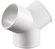
Excellent thought and design. I will be doing something much simpler, as for now I only have 1 EG4 Unit.... I am also going to Install my filter at the "head" (Where the fan at the wall is) , instead of at the EG4 itself, as this will be easier for me to access. I will make a T Connector to run one 4 inch duct to two connections for the intakes.... I like this idea.... so my Airframe controls speed of the Exhaust fans in tandem with the speeds of the vent intake fans..... so as it heats up in the utility closet, the fans will speed up to cool the inverter / Server closet.
Thanks again for your detailed explanations and designs! You are a great asset to this community!


I will follow up with my final findings.... After the Fan Mods, and Vented Closet / along with duct runs to the inverter!

~RandomPlanet
 
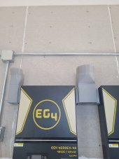
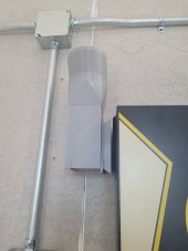
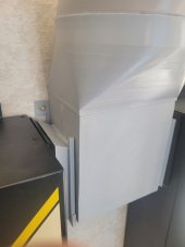
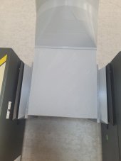
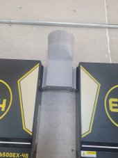
I've finished some 3D test prints with the duct adapters for the inlets on the outer located inverter and between two inverters. Also I've made some brackets where I will be able to slide these adapters upwards to be able to access the screws and filters to service them. On top of the round vertical outlets I want to attach standard flexible aluminum duct pipes. Later, I need to build a custom plenum to attach all five 6" ducts (from between the six inverters) and the two 4" ducts from the outside inverters. From this plenum I need to run a duct to the concealed indoor mini split unit.

20230602_084616.jpg 20230602_084607.jpg 20230602_084553.jpg
20230602_083703.jpg 20230602_083540.jpg 20230602_083533.jpg
20230602_083528.jpg
 
I've finished some 3D test prints with the duct adapters for the inlets on the outer located inverter and between two inverters. Also I've made some brackets where I will be able to slide these adapters upwards to be able to access the screws and filters to service them. On top of the round vertical outlets I want to attach standard flexible aluminum duct pipes. Later, I need to build a custom plenum to attach all five 6" ducts (from between the six inverters) and the two 4" ducts from the outside inverters. From this plenum I need to run a duct to the concealed indoor mini split unit.

View attachment 151479 View attachment 151482 View attachment 151485
View attachment 151486 View attachment 151487 View attachment 151488
View attachment 151489
Awesome! Looks great!
 
I've finished some 3D test prints with the duct adapters for the inlets on the outer located inverter and between two inverters. Also I've made some brackets where I will be able to slide these adapters upwards to be able to access the screws and filters to service them. On top of the round vertical outlets I want to attach standard flexible aluminum duct pipes. Later, I need to build a custom plenum to attach all five 6" ducts (from between the six inverters) and the two 4" ducts from the outside inverters. From this plenum I need to run a duct to the concealed indoor mini split unit.
Man! ..This is exceptional work! .. Great Job. I cant wait to see the finished project and see some of your Temperature readings!

***
I am working on my setup today .

Ive attached a few photos of vents and parts I intend to use for my duct work / cooling solution.

I have installed a custom fit Filter for my Intake vent to the power closet. The filter sits just inside a standard return vent, and looks acceptable to my wife (as this room is her Art Studio).
IMG_1981.jpegIMG_1983.jpeg

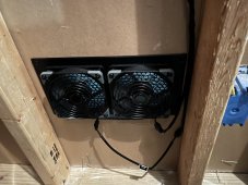
Here is the exhaust vent ( AC Infinity AIRFRAME T7 White, High-Airflow Cooling Fan System 17")
IMG_1984.jpegIMG_1982.jpeg
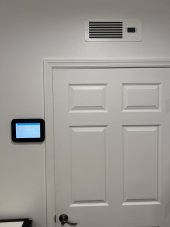
to the left is an inexpensive Amazon Fire tablet ( I have several of these throughout the home) ... I run Home Assistant at my home, and all home automation is tied to it ... (Including Solar of course)

I will be using 4inch Duct going from on of the fans on the intake to the intakes of the EG4
Screenshot 2023-06-02 at 1.49.28 PM.pngScreenshot 2023-06-02 at 1.48.51 PM.pngScreenshot 2023-06-02 at 1.48.15 PM.png

I ended up buying 4 of these NOCTUA Fans to keep things a bit more quiet:

Screenshot 2023-06-02 at 1.49.56 PM.png

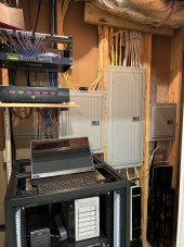
Here are a few more shots of the closet itself:
IMG_1985.jpegIMG_1986.jpeg

The third smaller Panel to the right is one that I installed and is load center for the EG4 ...

Ill post updates when i get the Duct work run....! Thanks so much to this thread for amazing ideas to get things cooler and more quiet!

~RandomPlanet
 
Quick follow up:

WELP ; I do not think my low draw 120MM Fan will supply enough pressure through about 17 feet of 4 Inch Duct to make a difference.
I do see the temps drop by a degree or two.... But I am wondering is it possible that I am doing the INTERNAL fans an injustice by sealing the intakes to force the draw through such a long 4inch Flex Duct ? Any ideas, or should i stick with the plan and assume that forcing the intakes to draw fresh A/C air with a Low Watt 120mm fan is better than nothing.???

~RandomPlanet

PS: I am all wired up and getting ready to but these 12v Fan Controllers in!
IMG_1988.jpeg
 
Ok !
So I got some stuff done today!

(1) I DID Reverse the fans in the EG4:

Screenshot 2023-06-04 at 6.26.57 PM.png


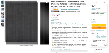
And to solve the filter problem I am going with a magnetic dust mesh kit like this :


Screenshot 2023-06-04 at 6.24.10 PM.png

(2) I installed the three 12v Fan controllers ... Does this look familiar ? :)

Screenshot 2023-06-04 at 6.28.06 PM.png


So I didn't get done in time to measure any PV ... but maybe tomorrow Ill check and see numbers!!!!


Still to DO:

I am going to rethink my duct work / fans / design. I may run duct on the exhaust side of things now that I have exhaust coming from the top of the unit!.... Stay tuned, Pictures will come.

Thanks all!

~RandomPlanet
 
Ok !
So I got some stuff done today!

(1) I DID Reverse the fans in the EG4:
And to solve the filter problem I am going with a magnetic dust mesh kit like this :
Good idea! Looking forward for your feedback about reversing the air flow...
(2) I installed the three 12v Fan controllers ... Does this look familiar ? :)
YES :cool:
So I didn't get done in time to measure any PV ... but maybe tomorrow Ill check and see numbers!!!!


Still to DO:

I am going to rethink my duct work / fans / design. I may run duct on the exhaust side of things now that I have exhaust coming from the top of the unit!.... Stay tuned, Pictures will come.

Thanks all!

~RandomPlanet
Good luck!
 
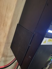
Here are the magnetic filters that I cut to fit the openings on the bottom/Sides of the EG4

IMG_2001.jpegIMG_1994.jpegIMG_1995.jpeg

I am slightly concerned that this type of filter doesnt trap dust as much like the Sponge Style (original) filters.....
But it does allow for better air flow, and theyb are SUPER easy to remove and clean!!!
I already DO See an improvement already in TEMPERATURES going down in the inverter! ..

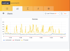
I will post some Solar Assistant Screen Shots after today's full sun event.
And then after completing the DUCT work , Ill show those as well.

todo still :

Finalize the two ducts going from the EXHAUST (Now TOP) of the unit to one of the exhaust fans of the t7 AIRFRAME above my closet door. This will be done tonight.

Cheers

~RandomPlanet
 

diy solar

diy solar
Back
Top