diy solar

diy solar

Replacing FANS inside the EG4 6500EX-48 to make it quiet

UPDATE:
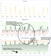
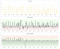
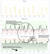
Ive attached a Graph that outlines some of the changes I have been making :
tonight I will install the 4 inch Ducts to exhaust the air out of the power closet with the help of one of the Airframe T7 Fans.
That graphic will be uploaded at the next day I get a comparable PV / Load day.

Here is the Snapshot from last 10 days:

Screenshot 2023-06-06 at 5.16.12 PM.png
 

Attachments

  • Screenshot 2023-06-06 at 5.16.12 PM.png
    Screenshot 2023-06-06 at 5.16.12 PM.png
    380.3 KB · Views: 6
Quick follow up:

WELP ; I do not think my low draw 120MM Fan will supply enough pressure through about 17 feet of 4 Inch Duct to make a difference.
I do see the temps drop by a degree or two.... But I am wondering is it possible that I am doing the INTERNAL fans an injustice by sealing the intakes to force the draw through such a long 4inch Flex Duct ? Any ideas, or should i stick with the plan and assume that forcing the intakes to draw fresh A/C air with a Low Watt 120mm fan is better than nothing.???

~RandomPlanet

PS: I am all wired up and getting ready to but these 12v Fan Controllers in!
View attachment 151628
Yeah a 120mm fan isn't going to work for such a length. Consider something like this, comes with 8 speed fan controller and at the lower speeds it's basically silent.

 
UPDATE:
Ive attached a Graph that outlines some of the changes I have been making :
tonight I will install the 4 inch Ducts to exhaust the air out of the power closet with the help of one of the Airframe T7 Fans.
That graphic will be uploaded at the next day I get a comparable PV / Load day.

Here is the Snapshot from last 10 days:
If I read it right, it looks like a huge success - about 15-20 degree Celsius (27-36 Fahrenheit) lower inverter temperature under PV charging and your typical load compared to the original setup?!

Btw. My active cooling project of the inverters will take a lot additional time - first I need to install a typical mini split in the RV garage to get the ambient down to be able to work on the ducted concealed mini split installation without melting ;) (now I have 95 Fahrenheit in the garage and it will likely climb to 100 over the next 10 days - even if the garage walls/ceiling and the garage doors are insulated - this is the price to pay when living in the desert ?).
 
I have two inverters in split phase. I installed the controllers in the L2 inverter today(not until after the batteries were fully charged, so minimal PV input) and wanted to share some initial findings.

Settings for all three controllers:
Po = min
Tu = 35C
Td = 20C

So far the L2 inverter has been running 3 to 5 degrees celsius warmer, but is significantly quieter. I am going to monitor the temps and play around with the settings on the controllers for a few days before installing them in the L1 inverter.
Hi,
just curious, do you have some news about your modding? Have you changed the L1 inverter also in the meantime and are you still happy with the results? What is your typical ambient temperature?

Thanks,
Frank
 
Can think of a few factors that may result in requiring a lot of noisy airflow through a system like the EG4, not that all of these directly apply to it but are possible reasons why it is what it is. One, the unit itself is not very deep which requires using smaller diameter fans. When you have smaller diameter fans in order to push as much air as a larger diameter fan that some other devices have you have to spin it faster which creates more noise. Two, not having temp controlled fans is annoying. Three, many electronic components have a "lifetime at temp" rating. You can get a component that lasts X hours at Y temp or one that lasts 10 or 100x longer at same temp. Generally the ones that last longer cost more for a given temp.. or you can use the cheaper ones by pushing a lot of airflow through to keep it cooler.
Your correct.. follow the money trail to find the truth..

as far as noise goes none of my Victron makes any noise Untill it’s really pushed…and then only the multi makes a modest fan noise…the 150/100 makes zero…so I aimed a super quiet 6 inch whisper fan at the bottom of the multi for experimenting and even when pushed the internal fan stays off or very quiet and the sound of the 6 inch fan is somewhat soothing…

little fans are annoying…
larger fans make you drowsy…
supplement your little noisy fan if it is temperature dependant for speed with a good fan so it will shut up…if it’s not temp dependant , then it should be…

What I’m using : 6 inch blade in metal frame with gaurd. .great CFM …..continuous duty for 70,000 hrs…( 8 years)… 3 watts draw on high….variable speed with speed ,timer ,temp ,alarms backlit display and remote…. super quite double ball bearing….$69.00 each…I have 4 …I use them for many purposes…
Seriously , a good fan..
 
The fans are loud, but I can deal I guess. Can I add to this and ask about a super high pitched noise that is unbearable. Just switched from a growatt to the EG4 6500 and it has a sound so high pitched I am sure anyone over 40 can't hear it, but I can and it is so loud it is giving me a headache. Gonna power down the system until I get it figured out I think.
When I was 30 I bought a fancy new high tech stereo amp with kazillion watts,.. replaced my old Marantz… that night my wife and me developed a terrible ringing and jaw clenching episode… gritting of teeth…felt sorta high…it made us sick over a few days… the new amp was playing through high end JBL floor speakers that reproduce high SPL of high frequency signal we couldn’t hear over the music but affected us… even the dogs hauled ass under the beds.. that’s what made me think of what was happening… probably 15 khz or higher ..?? It had a lot of garbage up high…
without being 30 and having a great system we would have never felt this…

I changed back to the old amp and lived happily ever after…

this sounds like what everyone is talking about…it will mess you up…
now at this age I can barely hear a dentist drill making that god awful sound…..
 
If I read it right, it looks like a huge success - about 15-20 degree Celsius (27-36 Fahrenheit) lower inverter temperature under PV charging and your typical load compared to the original setup?!

Btw. My active cooling project of the inverters will take a lot additional time - first I need to install a typical mini split in the RV garage to get the ambient down to be able to work on the ducted concealed mini split installation without melting ;) (now I have 95 Fahrenheit in the garage and it will likely climb to 100 over the next 10 days - even if the garage walls/ceiling and the garage doors are insulated - this is the price to pay when living in the desert ?).
I don't think the real delta is 15-20 Degrees Difference. BUT maybe ..almost 15 .... I Do Believe the reversing of the fans helps a lot ..... and Yes ; Getting Cold air into the "Closet" too helps..... However, the Noise reduction is significant! ..... Another decent day of sun today , and the Chart shows similar results for the inverter's reported Thermals. (I have not run the ducts from the Exhausts of the EG4 outside the power closet just yet).

Screenshot 2023-06-07 at 7.21.49 PM.png

TBC.

~RandomPlanet
 
UPDATE:

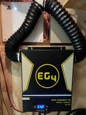
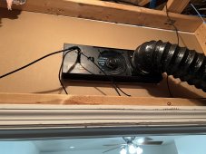
So I have added the duct work to the top two (NOW EXHAUST POINTS), since I reversed the Fans, and vented the hot air out of the Utility closet///In Theory , this should also help keep temps a bit lower in the closet, helping the servers and the EG4. ** See Pictures **

IMG_2007.jpegIMG_2008.jpeg


We shall see.

~Random Planbet
 
Sh*t, I've kinked my line set while trying to install my mini split to cool down the inverters (sorry it's a bit off-topic, but related...).

Some help appreciated:

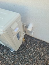
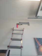
My house builder pre-wired the RV garage for 2 mini splits - everything is running nice inside the wall. Beside the existing electrical wiring and disconnect box, he also installed a 3 inch pipe for the line set and a small 1 inch pipe for the condensate drain line to connect. Now I have a real hard time time to push/pull the line set through the 3 inch pipe. The 3 inch pipe on the outside wall has a small angle (about 20-30°) where it comes out of the wall.

My problem is to push the (16ft) line set (together with the attached power cord and curled nicely with the non-Adhesive wrap which comes with the line set) from the outside up through the pipe. I've tried it a couple of times and it always stuck just about 1-2 feet before it would slide out on the inside wall unit (I think it will stuck where two pieces of the pipe are connected and the connector screw of the line set will hit against the inner pipe edge where the pipes are connected). Also I've tried to use conduit wire pulling lubricant, but no success. I've tried it also one time to push it down from the upper inside end, but it's horrible to stand on the ladder and handling the line set, also there is not enough space between the ceiling and the beginning of the pipe - this was the situation where I've kinked the line set.

I think I need to do it while pushing from the outside upwards is the correct procedure. Now I hope someone have an idea how pros are installing line sets in such a situation. I think about putting a sort of a rounded smooth hard plastic cap (e.g. from a small hard plastic bottle) over the line set connectors to make it easier to slide over the inside pipe edges.

In the attached picture I've marked the location of the 3 inch pipe with red and the 1 inch condensate drain pipe in blue color.

20230611_162608_small.jpg 20230611_162724_added_small.jpg

Any ideas?
Thanks in advance.
 
Last edited:
Sh*t, I've kinked my line set while trying to install my mini split to cool down the inverters (sorry it's a bit off-topic, but related...).

Some help appreciated:

My house builder pre-wired the RV garage for 2 mini splits - everything is running nice inside the wall. Beside the existing electrical wiring and disconnect box, he also installed a 3 inch pipe for the line set and a small 1 inch pipe for the condensate drain line to connect. Now I have a real hard time time to push/pull the line set through the 3 inch pipe. The 3 inch pipe on the outside wall has a small angle (about 20-30°) where it comes out of the wall.

My problem is to push the (16ft) line set (together with the attached power cord and curled nicely with the non-Adhesive wrap which comes with the line set) from the outside up through the pipe. I've tried it a couple of times and it always stuck just about 1-2 feet before it would slide out on the inside wall unit (I think it will stuck where two pieces of the pipe are connected and the connector screw of the line set will hit against the inner pipe edge where the pipes are connected). Also I've tried to use conduit wire pulling lubricant, but no success. I've tried it also one time to push it down from the upper inside end, but it's horrible to stand on the ladder and handling the line set, also there is not enough space between the ceiling and the beginning of the pipe - this was the situation where I've kinked the line set.

I think I need to do it while pushing from the outside upwards is the correct procedure. Now I hope someone have an idea how pros are installing line sets in such a situation. I think about putting a sort of a rounded smooth hard plastic cap (e.g. from a small hard plastic bottle) over the line set connectors to make it easier to slide over the inside pipe edges.

In the attached picture I've marked the location of the 3 inch pipe with red and the 1 inch condensate drain pipe in blue color.

View attachment 152701 View attachment 152702

Any ideas?
Thanks in advance.
Oh man.... Sounds NO FUN.
I am assuming you are using a fish tape. ?

Why not run the fish tape from the inside top, down to your outside angled entry point....
feed the set from the outside in ..... I find its useful if you can have two people..... one to PUSH/ feed in the line set .... the other to pull the fish tape.

Another idea is, HOW big is the mini split thyat attached to the wall in the picture you included? Could you make the cutout any larger to help with this?, or would it leave to much of a hole that would be seen ? (And or Patched After the lines are run) ?

Provide more clues , and im sorry if this seems obvious / already attempted. Keep us posted. Hope to get you along to the final steps!

~RandomPlanet
 
So .... Im Happy with the Changes Made on my EG4 6500EX-48 and the Utility Closet it lives in...

(1) Installed the 3 PWM Temperature Controller(s) on each of three fans : Big Shout and Thank you to @fmeili1 for this.
(2) Reversed the FANS in the unit such to draw cool air from bottom , and exhaust out the top.... (See My filter Hack up above)..
(3) install 4 120 MM Fans, two intake fans at the Bottom of the closet (Drawing AC in from finished room) ; two exhaust fans exiting the top of the closet....... a. I have the TWO exhaust points (Now at the Top) from the EG4 running into 4 inch duct, going to one of the 120MM Exhaust Fans....

All in all so far so great , the INVERTER fans are MUCH More Quiet, and running within Spec!

Here is a graph of the results...

Screenshot 2023-06-20 at 11.50.50 AM.png
 
So .... Im Happy with the Changes Made on my EG4 6500EX-48 and the Utility Closet it lives in...

(1) Installed the 3 PWM Temperature Controller(s) on each of three fans : Big Shout and Thank you to @fmeili1 for this.
(2) Reversed the FANS in the unit such to draw cool air from bottom , and exhaust out the top.... (See My filter Hack up above)..
(3) install 4 120 MM Fans, two intake fans at the Bottom of the closet (Drawing AC in from finished room) ; two exhaust fans exiting the top of the closet....... a. I have the TWO exhaust points (Now at the Top) from the EG4 running into 4 inch duct, going to one of the 120MM Exhaust Fans....

All in all so far so great , the INVERTER fans are MUCH More Quiet, and running within Spec!

Here is a graph of the results...

View attachment 153812
Looks like they're running much better than spec!

I wonder which is making more of a difference though, the change of the fans in the inverter or adding ventilation to the utility closet?
 
So .... Im Happy with the Changes Made on my EG4 6500EX-48 and the Utility Closet it lives in...

(1) Installed the 3 PWM Temperature Controller(s) on each of three fans : Big Shout and Thank you to @fmeili1 for this.
(2) Reversed the FANS in the unit such to draw cool air from bottom , and exhaust out the top.... (See My filter Hack up above)..
(3) install 4 120 MM Fans, two intake fans at the Bottom of the closet (Drawing AC in from finished room) ; two exhaust fans exiting the top of the closet....... a. I have the TWO exhaust points (Now at the Top) from the EG4 running into 4 inch duct, going to one of the 120MM Exhaust Fans....

All in all so far so great , the INVERTER fans are MUCH More Quiet, and running within Spec!

Here is a graph of the results...

View attachment 153812
AWESOME!

I'm looking forward to get my project done and hope to see the same good results (even without changing the air flow direction - but using active cooling).

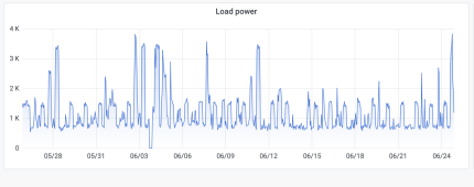
How much is you average inverter load in this scenario (hard to guess from the graphs)?
Are the fans speed up a lot if your have some short time peak loads?

Are the results still with your original temp PWN controller settings with Tu=35°C and Td=20°C ?

If yes, and while looking at the temperature graph, it looks like the fans are running only at about 30-50% of their max. speed?! Does this correlate with your subjective noise level and observations?

For me it's very exciting to see real life graphics with the modifications - I can't wait to finish my work...
 
AWESOME!

I'm looking forward to get my project done and hope to see the same good results (even without changing the air flow direction - but using active cooling).

How much is you average inverter load in this scenario (hard to guess from the graphs)?
Here is a graph of the Load Power :
Screenshot 2023-06-25 at 5.16.02 PM.png


Are the fans speed up a lot if your have some short time peak loads?
I honestly have not noticed the fans running to max during peak loads..... I tend to think under heavy PV loads is when the fans would race prior to the PWM Temp controllers.

Are the results still with your original temp PWN controller settings with Tu=35°C and Td=20°C ?
Yes ; Tu=35 degrees and Td=20 degrees celcius
My minimum fan speed is set to the 4th up from the lowest setting on all three fans. Max setting is well ; Max..

If yes, and while looking at the temperature graph, it looks like the fans are running only at about 30-50% of their max. speed?! Does this correlate with your subjective noise level and observations?
Yes.
For me it's very exciting to see real life graphics with the modifications - I can't wait to finish my work...
I would also consider the reverse air flow mod.... its NOT hard really.... but I DO know that you have gone through a lot of work 3d Printing your Active cooling Duct work...
 
Looks like they're running much better than spec!

I wonder which is making more of a difference though, the change of the fans in the inverter or adding ventilation to the utility closet?
Fair Point Adam.... I am guessing reversing the fans, and bringing air in from the bottom...... make a bit more difference than the venting of the utility closet.... the utility closet is unfinished and thus has no ceiling to TRAP the hot air........ such that the heat can dissipate to in between the floors of the house....
 
I have two inverters in split phase. I installed the controllers in the L2 inverter today(not until after the batteries were fully charged, so minimal PV input) and wanted to share some initial findings.

Settings for all three controllers:
Po = min
Tu = 35C
Td = 20C

So far the L2 inverter has been running 3 to 5 degrees celsius warmer, but is significantly quieter. I am going to monitor the temps and play around with the settings on the controllers for a few days before installing them in the L1 inverter.


View attachment 148987
Something I had never noticed till I was talking to someone this morning, but you can see in this image (it's a better one than I had), the intake on the top right of the unit it half blocked by that plastic shroud.
 
I'm sure that plastic is there to direct air down through the machine. If anything, it should stick up higher.

On the left side, 1/3 of the intake is covered.
 
I'm sure that plastic is there to direct air down through the machine. If anything, it should stick up higher.
I'm sure it is because there's 2 fans located at the bottom of the shroud. The issue that I see is if you block the air intake, it's much harder to cool the unit down.
 
I don't think it is blocking the intake like the left side is. You can only see half of the intake from the front view, but the air doesn't need to go to the front.

Unless what I can't see.....is there a flap on the right side of the plastic that extends to the back of the unit?
 
Now that make sense (well, it explains what you are saying...but doesn't make sense why they'd do that). Everyone needs to take the chopper to that piece then.
 
Now that make sense (well, it explains what you are saying...but doesn't make sense why they'd do that). Everyone needs to take the chopper to that piece then.
Unfortunately it's like my house when we do a renovation. We just had to stop asking "why in the world would they do X"...
 
@RandomPlanet are the magnetic dust mesh kit filters working out? I am thinking about reversing the fans, and your solution for filters seems to be the simplest to clean. I'm thinking the extra surface area might allow the interval to be less frequent than monthly depending on the environment.
 
i bough a rebuilt eg4 6500ex unit from signiture, and when first turned on it sounded like someone parked a sesna air plane in my garrage, and since it was working on new lithium batteries at 48+volts with only half charge the fans were going to town. that night after sun went down with verry little load
on the system they continued to run full bore, next day same thing until the batteries ballanced out and the charge droped off and the fans calmed way down. and tonight same load but fans much calmer. it was like the thermostat was stuck. i thnk a different fan could help a lot if you can keep the cfm about the same.. learned from computer fans that there a big difference in quallity and sound for same cfm. read the spec for the noctua fan it runs from 400rpm to 2000 rpm.
 
There is a simple option which also helps to reduce the temperatures of the EG4-6500EX.

Because the hot air outlets are on the bottom of the unit and the cooling air intakes are at the top, there is a thermal short circuit (already discussed here). I've 3D printed 45 degree air shields to isolate (at least a bit) the intake from the outlet. The 45 degree angle helps to let the hot air rising without blocking it and the cold air from above the shield will not be mixed too much with the hot air.

This cheap option reduced the temperature difference to about 5 degree celsius between intake and outlet, which is anyway a good thing to help the inverter. But together with the modded fans with a temperature based PWM fan speed circuit, it also reduces the noise (even without active cooling with an A/C).

This is how it looks like with the installed air shields:
20231112_074036.jpg

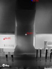
And here is the thermal camera picture which showing the temperature difference between above and below the air shield:
1699800135055.jpg

If it's of interest, I can provide OpenSCAD or STL files if someone wants to do the same.
 

diy solar

diy solar
Back
Top