This is probably about average for a cheap AIO unit.
Bear in mind that there is no "truth in advertising" in regards to solar. You can say pretty much whatever you want as long as it sells stuff.
The only way I know of to create "pure sine wave" AC (< 1% THD, in my opinion) involves using a class AB amplifier or a high-quality Class C amplifier.
Neither of those approaches is very power efficient or cheap, so aren't used for inverters.
There is another way to generate very low THD waveforms with high power efficiency, but its not cheap and not really cost competitive commercially.
Several individual square wave inverters driving individual transformers can have different voltage secondaries all connected in series, and is then able to generate any type of output waveform. Its a kind of high power direct digital to analog conversion method, at the multi kilowatt level (or any power level).
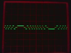
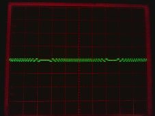
It produces a stepped output waveform, but the steps can be made very small.
Each inverter produces a square wave output with three possible logic levels, a negative voltage output, zero voltage, or a positive voltage output.
One inverter has 3 possible voltage steps. Two inverters 9 steps, three inverters 27 steps, and four inverters 81 steps.
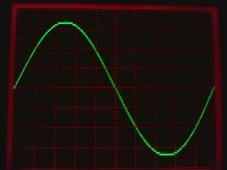
Four inverters combined, can produce an unfiltered output of a measured 0.85% THD.
Its very power efficient because the square wave inverters are hard switched at low frequency. The largest inverter switches at only 50/60Hz.
The smaller inverters are slightly more frantic, but still only switch at relatively low audio rate.
My own "Warpverter" works on this principle. Its not commercially viable because of the cost of winding four transformers, but if you wind your own, its an excellent way of making a very high powered robust inverter with excellent performance for very reasonable cost.
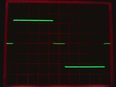
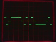
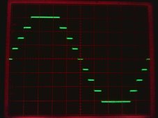
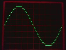
The output waveforms across each secondary winding looks like this:
The inverters are hard switched, the difference in voltage is produced by the primary/secondary ratios of the transformers.
The waveforms below are shown with the correct relative amplitudes on the crappy difficult to photograph analog oscilloscope I had at the time.
Largest inverter +/-225v, second inverter +/-75v, third inverter +/-25v, fourth inverter +/-8.3v.
Peak amplitude 225 + 75 + 25 + 8.3 = 333.3v
RMS value 235.6v