diy solar

diy solar

Power up review PowMR (SRNE) POW-LVM3K-24V-H

So allowing for temperature correction on hot days what do you suggest that you have Vmp be above Vmppt-min? An earlier discussion about this with Hedges I had he seem to suggest about 10%. That would put a Vmp rating for my AIO at 120v+10% = 132vDC
I think you asking what I recommend in terms of Vmp @ STC, meaning 25C / 77F.

So we’re going to assume you’ve properly designed your string to start up your MPPT every morning and we’re just looking at what point Vmp of the string translates to too much lost potential energy to be worthwhile.

First, I’d recommend focusing on average temps on the hottest months you care about and use PTC rather than STC. PTC is based on 20C ambient, so panel temperature will typically be higher than 25C but that is realistic.

By comparing PTC power rating to STC power rating you can calculate what temperature the panel is at operating in 20C ambient and from that calculate the realistic Vmp at 20C ambient.

If you care about worst-case losses at higher temperatures than 20C, adjust from there.

Now you have the ideal Vmppt_min under the highest ambient temperatures you care about.

If Vmppt_min is only 10% higher than that adjusted Vmp_min, power loss will be less than 10% -probably closer to 8%.

Current at higher voltage will be lower than Imp (adjusted) but by less than 10%. You can attempt to guesstimate from the radiance power curves (attempt to bracket how much lower power is at 110% Vmp) but it’s tough (my 380W panels deliver over 350W @ 110% Vmp, meaning less than 8% loss at 110% Vmp).

There is a wide ‘flatspot/hump and my advice would be to try to avoid going significantly out of it and losing more than 10% potential power.

The hump on my panels is close to +/-5V from Vmp of 40V, so let’s say +/-12%. You’re losing little-enough power in the flatspot that it’s certainly not worth abandoning your project or perturbing unnatural acts or spending lots of $$$s to get closer to Vmp.

So I’m basically agreeing with what hedges has recommended but suggesting to do so based on adjusted Vmp under estimated operating condition (adjusted PTC for the highest ambient temperatures you care about) rather than just using STC (or NOCT).
I am going to have to read your response several times (o_O ack!) before I understand it (perhaps early tomorrow before my afternoon dementia sets in).
 
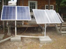
OK I think I am understanding your post, Fafrd. One additional consideration for my setup (8S2P) that I had to make was for my panel setup and location. My panels are mounted 2 to a metal post 5 feet apart for the majority of them. Due to location the sun hits them from the left and exposes them one by one as it rises until they are all in full sun by Noon (this time of year). Ideally they work best in parallel but I needed as I mentioned a higher minimum voltage to run this new AIO. By using the 8S2P I get some production before Noon.

Someone with a better setup/location using 100w RV panels would likely be better served just going one string of 16 in series. That gives 352Voc and 288Vmp which would place both Vmppt_min and Vmppt_max in good ranges.

P1010002.JPG
 
OK I think I am understanding your post, Fafrd. One additional consideration for my setup (8S2P) that I had to make was for my panel setup and location. My panels are mounted 2 to a metal post 5 feet apart for the majority of them. Due to location the sun hits them from the left and exposes them one by one as it rises until they are all in full sun by Noon (this time of year). Ideally they work best in parallel but I needed as I mentioned a higher minimum voltage to run this new AIO. By using the 8S2P I get some production before Noon.

Someone with a better setup/location using 100w RV panels would likely be better served just going one string of 16 in series. That gives 352Voc and 288Vmp which would place both Vmppt_min and Vmppt_max in good ranges.

View attachment 157920
Funny, I’m in the exact same situation as you (but due to moving shade on one roof face in my case).

My current DC-coupled array is 1S3P oh half-cut panels for precisely this reason (get 100% output from any half-panel as soon as it is clear of any shading).

I’m adding 6 more 60-cell panels and cannot stay parallel and as I debate between 3S2P and 6S1P I’ve come to the conclusion that the second-best choice to full parallel is full serial.

I’ll need an inverter that can handle a Voc-max of 250VDC but the lower the Vmppt_min the earlier I can start getting output.

The SRNE 10kW split-phase hybrid I’m considering has a Vmppt_min of 125V, so this means I only need 3 fully unshaded panels to start getting full output from those 3 panels.

Vmp is 30.2V (@25C) so 4 unshaded panels will have Vmp of 120.8V - 6 x 0.7V (from 6 activated bypass diodes) = 116.6V, so I’ll be running at 2.8V below Vmp (-10%).

But that’s way better than waiting for all panels to be shade-free.

For 2 differently-oriented strings, you’ll get the most output by having 2 independent MPPTs.

If that’s not an option, a 16S2P might actually be preferable to 8S2P.

You’ll get full output from the early morning panels in the morning while bypassing the afternoon panels, full output from all panels at midday, and full power from the afternoon panels by bypassing the morning panels in the afternoon.
 
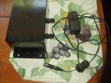
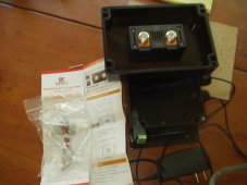
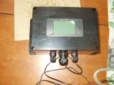
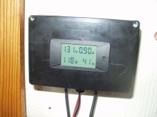
Just got done installing my PV shunt and meter. Not terribly happy with the box I bought for it as the plastic was easily scratched by my jig saw and it is rather malleable and not stiff as I would like. This means the meter that is a snap in fit does not hold the best. But it is working and showing that a fair amount of watts are being delivered even before the sun is on the panels.
 

Attachments

  • P1010004.JPG
    P1010004.JPG
    264.3 KB · Views: 7
  • P1010006.JPG
    P1010006.JPG
    283.4 KB · Views: 6
  • P1010007.JPG
    P1010007.JPG
    270 KB · Views: 7
  • P1010008.JPG
    P1010008.JPG
    303.4 KB · Views: 7
  • Like
Reactions: mib
Shunt operates at PV voltage bias away from ground. Can it withstand voltage delta from logging equipment that connects to it?

I've used I2C or SPI isolators that have multiple kV test voltage, but intended for only a couple hundred volts. Something with transformer isolation might have higher isolation given dielectric bobbins, or as low as what enamel wire insulation is good for. Probably rated 600V. many plastics or enamel (likely actually polyester) are good for about 1000V/mil.

I've seen panel meters with LCD operating at a few thousand volts bias. That was in a research lab, and I wasn't confident it was good for human safety. I though a separate window over it would be better to prevent shock, rather than just LCD glass and bezel. Some 10's of kV equipment had extension plastic rods on potentiometers. In that case I would consider insulator, then metal piece with ground strap or sliding contact to ensure any surface leakage or conduction through contamination was drained to ground.
 
No logging equipment other than shunts own meter. Very basic in nature. It replaces having to use a clamp on and a DMM to figure wattage. I ran a similar PV shunt setup for a year on my previous AIO. This particular one is good for test voltage up to 300vDC (the PV array is 176Voc) and the shunt is 50 amp.

Handy since my AIO's measurement of incoming PV watts is not accurate.

ETA: Yesterday my 1600w PV array produced 5.03 kWh based on the PV shunt. Not bad considering most of the day was cloudy and with heavy haze. I expect better today with more sun though it is hot outdoors. (95F at noon)

Continuing review. This new PowMr SCC does a better job than my #2 EAsun unit in terms of percentage yield from panels. The PowMr is getting 72% from its 8S2P 1600w array while the EAsun is getting 65% from its 3S2P for the same time of day and sun condition.
 
Last edited:
  • Like
Reactions: mib
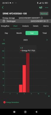
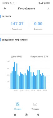
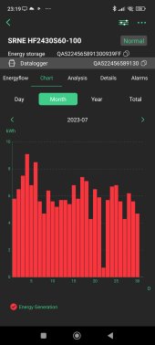
Handy since my AIO's measurement of incoming PV watts is not accurate.
i change the output to 220 volts in your case 120 volts

after all, there is an AIO efficiency and a DC line is noticeably less than an alternating one
 

Attachments

  • Screenshot_2023-07-30-23-18-08-980_com.eybond.smartclient.ess.jpg
    Screenshot_2023-07-30-23-18-08-980_com.eybond.smartclient.ess.jpg
    94.5 KB · Views: 9
  • Screenshot_2023-07-30-23-18-33-700_com.coolkit.jpg
    Screenshot_2023-07-30-23-18-33-700_com.coolkit.jpg
    84.9 KB · Views: 8
  • Screenshot_2023-07-30-23-19-03-394_com.eybond.smartclient.ess.jpg
    Screenshot_2023-07-30-23-19-03-394_com.eybond.smartclient.ess.jpg
    111.5 KB · Views: 8
I try to limit max AC loading on the AIO to around 2500w, preferably less than 2000w. It seems to work fine with that as a limit.
 
I try to limit max AC loading on the AIO to around 2500w, preferably less than 2000w. It seems to work fine with that as a limit.
I meant ac out. Maybe you also meant that? Limit by simply not using to many appliances at once? You are unable to try and max pv power in I guess? Think I saw your pv setup in other thread. Looked quite small.

Reason why I ask is that powmr earlier units seem to have been total rubbish's, more specifically their 60 amp ssc but the newer aio's seem to be of same quality as growatt and epever
 
Can these PowMr be run in parallel, been thinking of getting one of the 5000 watt units but may have to run 2 eventually.
some definitely can up to 6 units, some cant I think.

 
I meant ac out. Maybe you also meant that? Limit by simply not using to many appliances at once? You are unable to try and max pv power in I guess? Think I saw your pv setup in other thread. Looked quite small.

Reason why I ask is that powmr earlier units seem to have been total rubbish's, more specifically their 60 amp ssc but the newer aio's seem to be of same quality as growatt and epever
Yes I was referring to the 120vAC out loading. I could indeed max it if I wanted to since I have a 120vAC 2000w water heater and several space heaters I could use for a load test. But my use is not to test the unit for full out and beyond. I can not afford to test to destruction like a lab or someone like Will. Just a retired old nut living in the woods. Mostly on these Chinese thingies it is not a good idea to attempt to run full out anyway.

I have seen it to 2800w briefly while running a microwave, refrigerator and house water pump. I do practice load management.

My PV setup for this inverter is 1600w consisting of 16-100w panels in a 8S2P arrangement.

This is not PowMR manufacture. It is a SRNE rebadge. There is a ton of them with different names out there.
 
Last edited:
Something to be aware of. This high voltage AIO does put 62.5vAC out on the PV wires. It can lead to a hot panel frame if that frame is not electrically connected to other frames. Many of my panels are mounted to metal poles but I did have a few that were on wood based racks and those when measured to the pole mount ones is where my DMM measured the 62.5vAC. it is of a very low amperage though that would not light up a small test bulb. But I did get shocked the other day when trying to hook up my shunt and not completely de-energizing the AIO. (Pretty dumb to not always check a circuit dead before working on it).

My solution was to wire the frame of the panels that are wood mounted ones to the frame of the nearby metal poll mounted ones.
Isnt your aio ac out ground cable bonded to an earth rod driven down into the ground ? I _think_ ac out ground and aio chassi ground plug is bonded internally so you can connect ground cable between that and earth rod
 
Isnt your aio ac out ground cable bonded to an earth rod driven down into the ground ? I _think_ ac out ground and aio chassi ground plug is bonded internally so you can connect ground cable between that and earth rod
The AIO has a chassis ground that hooks to my house ground. It is NG bonded when operating from inverter and uses the Main panel NG bond when in Bypass. None of these should be connected to the PV input. How it gets the AC voltage on them is a function of the AIO's electronics and is beyond my level of knowledge to explain the path.
 
The AIO has a chassis ground that hooks to my house ground. It is NG bonded when operating from inverter and uses the Main panel NG bond when in Bypass. None of these should be connected to the PV input. How it gets the AC voltage on them is a function of the AIO's electronics and is beyond my level of knowledge to explain the path.
Just checked my unit. It has battery negative, Ac n and ac ground bonded to earth rod. My pv negative and above mentioned have 100v ac potential and 200v dc potential between them.

On epever charge controllers pv negative in and battery negative out are bonded but aparantly they are not on these powmr units.


Maybe a bond between pv negative and battery negative should be made?
I don't have enough electronic knowledge to know if that would be a good idea or not especially with a high voltage MPPT type SCC. A PWM it likely is the default arrangement.
 
I don't have enough electronic knowledge to know if that would be a good idea or not especially with a high voltage MPPT type SCC. A PWM it likely is the default arrangement.
Im not doing that either. Its some weird
I don't have enough electronic knowledge to know if that would be a good idea or not especially with a high voltage MPPT type SCC. A PWM it likely is the default arrangement.
The manual said that the aio housing is hot during use and not to touch it.. ? not sure if they meant hot as in it is energized or just hot as in temperature
 
How is your powmr treating you sofar @Mattb4 ?

Mines doing just fine when it comes to running my household.

The SRNE pc monitoring software tho did not want to work with my rs485-usb cable but worked fine with usb a-b cable.
Data collecting is a bit wonky and get stuck if you work with to many tabs at once in the SRNE app.
 
I am having no issues. The MPPT in it is better that the one in the EAsun I replaced. The AIO's fan is quieter and it runs my household loads nicely with 7-8 hours of A/C during these near 100F days. I would consider replacing my #2 EAsun AIO with another PowMr one other that it is working plenty good enough itself. Plus I do have the spare available if it decides to stop.

I do not bother with monitoring my units other than the PV shunts and din rail AC power meters with local readouts.
 

diy solar

diy solar
Back
Top