diy solar

diy solar

JK BMS CAN bus comms now possible for inverters that support Goodwe and Pylontech batteries

I did the tests below with a battery at +/- 53.1V
I set the offset to 3V to match the condition of the box marked "A".

Under these conditions when booting the ESP32 the charging status should be on Bulk but we remain stuck on Wait.

Why ?

Normal operation is for it not to charge till Voltage is below: absorption_v - rebulk_offset:
You don't want a rebooting esp32 to be constantly charging the battery.
Think of an edge case where the ESP is rebooting every 30 seconds, it will be constantly microcycling the battery.
My Interface boards do not reboot, I have them up for years, so under normal operation it charges up the battery and then waits for the Voltage to drop as per below:

55.2 - 3 = 52.2 this is where it will request bulk.
53.1 is above 52.2 so it will wait till the voltage is below 52.2v as per normal operation.

Your issues seem to be your rebooting ESP32 fix them and it works as intended.

Edit you are using very old code, Interface boards are shipping with V1.22 FW.

Regards.
 
Last edited:
Normal operation is for it not to charge till Voltage is below: absorption_v - rebulk_offset:
You don't want a rebooting esp32 to be constantly charging the battery.
Think of an edge case where the ESP is rebooting every 30 seconds, it will be constantly microcycling the battery.
My Interface boards do not reboot, I have them up for years, so under normal operation it charges up the battery and then waits for the Voltage to drop as per below:

55.2 - 3 = 52.2 this is where it will request bulk.
53.1 is above 52.2 so it will wait till the voltage is below 52.2v as per normal operation.

Your issues seem to be your rebooting ESP32 fix them and it works as intended.

Edit you are using very old code, Interface boards are shipping with V1.22 FW.

Regards.

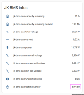
I don't have any stability or reboot problems with my ESP32, it was a suggestion that I mentioned following the strange behavior that I noticed but I monitor the uptime now and it is stable, no problem of this side. It's only 5:44:50 because I made the videos this morning with reboot test to show them to you here. Tomorrow it will be 24 hours more!

I can understand that there is a risk of microcycling in this case, okay.

On the other hand, there is also a problem with leaving a battery in 'Wait' because its voltage is between (absorption_v) and (absorption_v - rebulk_offset) but its SoC is below 50% which is entirely possible. Simply connect the ESP32 just when the battery is charging with 30A or more.

It is possible to improve the code to take both scenarios into account.

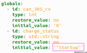
Can you tell me why you programmed a 'Startup' procedure?

This procedure does not work for the reasons I cited in the previous post. Do the test yourself to see.

1695293886408.png

1695293933169.png


1695293047336.png
 
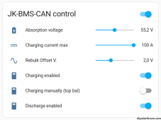
absorption_v: "55.2"
rebulk_offset: "2.5

55.2 - 2.5 = 52.7V

Normal operation is for it not to charge till Voltage is below: absorption_v - rebulk_offset:

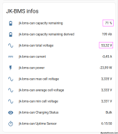
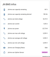
So according to you this battery (at rest) which is at 71% and 53.32V is no longer allowed to charge?

It's a 280Ah pack, there are 199A left, so I can still charge 80Ah.

1695294899047.png
 
Can you tell me why you programmed a 'Startup' procedure?
I think I programed it initially, and then made more changes to fix other status, and when I tested it worked as it should.
I think at some point I changed my mind and decided that startup charging was not I good idea.

In later code it is very different, and the whole code base does not run till after a startup delay to give the BMS code time to update. (BMS code runs separately).

The offset at 2.5v with no load in reality is about SOC 80-90%, after charging the cells they with drop a fair bit of voltage in a few hours.
With a small load of 20-40A it very quickly drops below the 2.5V offset.

You can set the offset to whatever works for you.
 
So according to you this battery (at rest) which is at 71% and 53.32V is no longer allowed to charge?
Yep that's correct, because in real use case(for most people) the battery voltage will drop the surface charge in a few hours.
It will also not be at 71% after discharging all night.
When the morning rolls around it will be/have been below the offset at some point, and will be in bulk mode.
Voltage sags quickly at the knee of the charging curve.

It's why its configurable, if you want the offset less set as it pleases you!!!

I would suggest you run it in real world use case before you start throwing stones, you will see it works very well.
 
Last edited:
In later code it is very different, and the whole code base does not run till after a startup delay to give the BMS code time to update. (BMS code runs separately).

Well, I see that you have noticed the same problem that I mentioned regarding the fact that it is necessary to wait a little to receive the information from JK-BMS.
 
Well, I see that you have noticed the same problem that I mentioned regarding the fact that it is necessary to wait a little to receive the information from JK-BMS.
It's not really a problem here, it becomes troublesome when I wrote the MuliBMS code, and adding a new pack would send alarms to the master.
 
It's a 280Ah pack, there are 199A left, so I can still charge 80Ah.
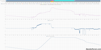
Here is how it works in the real world when you are actually using the battery as intended.
You will see the battery has gone back to bulk at 17:30 right as it starts to discharge.
I'm charging to 56V (testing if balancing better, spoiler it does) with a 2.5V rebulk_offset

1695298027043.png
 
Last edited:
Here is how it works in the real world when you are actually using the battery as intended.

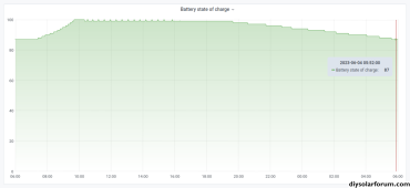
This is what was happening in the real world at my house on 03.06.2023.

At 6:00 AM I am still at 87% SoC and 53V.

This is very different from what happens now or in winter.

Fortunately we can configure the 'rebulk_offset' value as desired and even improve the script.

Long live open source.

Thank you for your work ;)

1695303548850.png
 
This is what was happening in the real world at my house on 03.06.2023.
By my rough cals you have used 36AH in 11 Hours = 3.27A * 53v = 176.58 W average, which is basically just a fridge running.
Do you have the whole house connected or just a few circuits, or is no one living there?
In cases like these there is probably no need to charge every day, just charge every 2, or 3 days, your battery is big enough, charging every day is just cycling the battery for no real need.
Adjust the Rebulk_offset to cater for your anemic usage.

:ROFLMAO: maybe a weekend when we were away from home ;)
 
I simplified the code, it has exactly the same behavior as your version V1.13.3 except that I added a 'Rebulk Offset V.' slider which allows to exit the 'Wait' state if necessary without needing to activate 'Bulk Manually'.

This therefore prevents microcycling in the event that the ESP32 is unstable and will reboot.

Behavior video :


C++:
            // +---------------+
            // | Charge Status |
            // +---------------+
       
            // Disabled : charging disabled if BMS or HA switch is OFF
            if ((!id(charging_switch).state) | (!id(inverter_charging).state)) {
               id(charge_status) = "Disabled";
            }
            // Wait : all charging swith is ON and charge status is 'Disabled'
            else if ((id(charging_switch).state) & (id(inverter_charging).state) & (id(charge_status) == "Disabled")) {
               id(charge_status) = "Wait";
            }
            // Bulk Manually : forced battery charging via HA 'Charging manually (top bal)' switch
            else if (id(inverter_chg_on).state) {
                id(charge_status) = "Bulk Manually";
            }
            // Wait : after switch OFF 'Charging manually (top bal)' HA switch
            else if ((!id(inverter_chg_on).state) & (id(charge_status) == "Bulk Manually")) {
               id(charge_status) = "Wait";
            }
            // Bulk : if Batt. V. <= ( Absorption V. - Offset V. ) ? by default is 55.2-2.5 = 52.7 V
            else if (id(total_voltage).state <= (id(charging_voltage).state - id(rebulk_offset).state)) {
                if (id(absorption_script).is_running()) id(absorption_script).stop();
                id(charge_status) = "Bulk";
            }
            // Absorption : if Batt. V >= ( Absorption V. - 0.05 V ) ? by default is 55.2-0.05 = 55.15 V
            else if (id(total_voltage).state >= (id(charging_voltage).state  - 0.05)) {
                if (id(charge_status) == "Bulk") {
                    id(charge_status) = "Absorption";
                    // 10 % from top start absorption timer
                    if (!id(absorption_script).is_running()) id(absorption_script).execute();
                }
            }
 
Last edited:
allows to exit the 'Wait' state if necessary without needing to activate 'Bulk Manually'.
If you increase the absorption voltage slider(and then return it to normal) it will also trigger the battery into Bulk mode
eg if you move the absorption slider to 57.6 - 2.5v = 55.1V battery voltage below this would trigger Bulk.
 
I would suggest you run it in real world use case before you start throwing stones, you will see it works very well.

Hi @uksa007

My goal is not to throw stones, I just tested and analyzed your script in different situations and I am telling you what I discovered with the sole aim of improving it.

That said, this is probably useless because you have already done it in the new version 1.16 which I will happily test when it is available.

1695453477193.png

Your issues seem to be your rebooting ESP32 fix them and it works as intended.

Interestingly, you wrote in black and white that you solved a daily reboot bug in the case where there is no connection of the ESP32 with HA.

During our discussion regarding my problems where I mentioned a possible instability of my ESP32 you never asked me if the ESP32 was well connected with Home Assistant.

And indeed I did not have an HA server, I added an HA server afterwards to monitor the uptime of the ESP32 which has been stable since it was connected with HA.

I understand better where the initial instability problems came from.

My ESP32 has not restarted since I sent the last code Thursday evening around 19:00.

1695454991648.png

1695454498797.png

Once again, thank you for your work which is much appreciated.

I like to test things thoroughly and find the little beast.

I wish you a nice day ;)
 
Last edited:
JK is releasing a new BMS compatible with a large number of inverters.

It will soon be tested on Andy's channel.

More info in the links below.

 
Hi uksa007. Thank you for your efforts on this project.
I'm a newbie in ESP32, so I would appreciate any help.
I have a Deye SUN-6K-SG03LP1-EU and I'm trying to connect it to a JK Bms with https://github.com/Uksa007/esphome-jk-bms-can solution.
ESP32 seems to be at infinite loop. Here are sone logs:
[18:44:46][D][text_sensor:064]: 'jk-bms Charging Status': Sending state 'Disabled'
[18:44:46][main:244]: send can id: 0x351 hex: ec 1 0 0 0 0 c2 1
[18:44:46][main:245]: send can id: Charge Status Disabled
[18:44:46][D][canbus:033]: send standard id=0x351 rtr=FALSE size=8
[18:44:47][W][component:204]: Component interval took a long time for an operation (1.02 s).
[18:44:47][W][component:205]: Components should block for at most 20-30ms.
[18:44:47][main:258]: send can id: 0x355 hex: ff ff ff ff
[18:44:47][D][canbus:033]: send standard id=0x355 rtr=FALSE size=4
[18:44:48][W][component:204]: Component interval took a long time for an operation (1.01 s).
[18:44:48][W][component:205]: Components should block for at most 20-30ms.
[18:44:48][main:272]: send can id: 0x356 hex: ff ff ff ff ff ff
[18:44:48][D][canbus:033]: send standard id=0x356 rtr=FALSE size=6
[18:44:49][W][component:204]: Component interval took a long time for an operation (1.01 s).
[18:44:49][W][component:205]: Components should block for at most 20-30ms.
[18:44:49][main:289]: send can id: 0x35C hex: 0 0
[18:44:49][D][canbus:033]: send standard id=0x35c rtr=FALSE size=2
[18:44:50]E (18111) task_wdt: Task watchdog got triggered. The following tasks did not reset the watchdog in time:
[18:44:50]E (18111) task_wdt: - loopTask (CPU 1)
[18:44:50]E (18111) task_wdt: Tasks currently running:
[18:44:50]E (18111) task_wdt: CPU 0: IDLE
[18:44:50]E (18111) task_wdt: CPU 1: IDLE
[18:44:50]E (18111) task_wdt: Aborting.
[18:44:50]
[18:44:50]abort() was called at PC 0x400fe550 on core 0
[18:44:50]
[18:44:50]
[18:44:50]Backtrace:0x400837a5:0x3ffbe9bc |<-CORRUPTED
WARNING Found stack trace! Trying to decode it
WARNING Decoded 0x400837a5: panic_abort at /Users/ficeto/Desktop/ESP32/ESP32S2/esp-idf-public/components/esp_system/panic.c:402
[18:44:50]
[18:44:50]
[18:44:50]
[18:44:50]
[18:44:50]ELF file SHA256: 0000000000000000
[18:44:50]
[18:44:50]Rebooting...

As I understand that is because the inverter does not respond to CAN bus. Isn't it?
I have checked the TJA1050 output with an oscilloscope and it has some output signals.
Checked on pins 4 and 5 (as per Deye manual) at the inverter and there is silence there.
Is that expected that the inverter just listens without any signals to the CAN? (I don't think so, but I'm not sure after all). Is my inverter CAN output broken? Do you have any idea what I might be doing wrongly?
I have spent a couple of days on this stuff and I am completely stuck.
 

Attachments

  • 2023-10-04_19-58-57-361.jpg
    2023-10-04_19-58-57-361.jpg
    664.1 KB · Views: 6
@Yevhen

I have exactly the same model as you.

Can you verify that the points below are correct ?

If you make modifications, you may need to reboot the ESP32 afterwards.

1696589309518.png

1696589342133.png

1696589245452.png

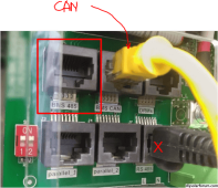
CAN H on RJ45 PIN 4 and CAN L on PIN 5.

1696590185940.png


No crossing !


1696589802521.png

Another point to know, in version 1.13.3 there is a bug, if your ESP32 is not connected to a Home Assistant server there are daily reboots.
 
Last edited:
@Sleeper85 Your post was really helpful!
You mentioned "Inverter port. Not cable RJ45" and "No crossing !" and that was exactly my issue: I have crossed CanH and CanL.
I have some uart communication issues left but I'll figure them out (I believe).
Thank you so much!
 
I'm trying to better understand the project, so a couple of questions if you don't mind, guys.
1. Why do we have "id(capacity_remaining)" instead of "id(state_of_charge)" here? Is that a bug or is it by intention?
2. Why do we use rebulk_offset as a number here? In my case, I'm getting charge status "Wait" when SOC is about 60%. Maybe it is better to use SOC here as well?
1. There is no such value id(state_of_charge), id(capacity_remaining) is the SOC.

2. SOC is often not accurate and can drift over time if it doesn't get reset.
Charging to a set voltage is the most accurate way.
Adjust rebulk_offset lower to trigger charging when you what it.
The default rebulk_offset of 2.5V will trigger charging at about 90% SOC if there is a small load of ~10 to 20A.

Consider supporting the project by purchasing a hardware interface, or becoming a Patreon member.
 
Hi- @Starman I'm trying to get this up and running with my Sofar S3000 and read that you've managed this.

I've purchased one of @uksa007 's pre-built boards and connected it to my Wi-Fi, then connected the JK adapter board to the inverter's CAN socket using a standard ethernet cable.

When I access the ESP32's web server I can see all of the BMS's settings and the log scrolling on the right, mostly with BMS status.
Then there are these lines regarding communicating with the inverter:

Code:
23:19:04    [I]    [main:181] Waiting for inverter response can_305_rx: 25
23:19:04    [I]    [main:181] Waiting for inverter response can_305_rx: 26
23:19:04    [I]    [main:181] Waiting for inverter response can_305_rx: 27
23:19:05    [I]    [main:181] Waiting for inverter response can_305_rx: 28
23:19:06    [I]    [main:181] Waiting for inverter response can_305_rx: 29
23:19:07    [I]    [jk_bms:062] Status frame received

I followed your advice and switched the inverter to general lithium, but I'm seeing this on its display:
1698969742520.png

I saw you mention "I use 16s and sofar me3000sp and it works well. Using the goodwe protocol." - do I need to select this protocol somewhere? If so, how?

"on my sofar me3000sp pin 4 is can H and pin 5 is can L." - does this require making up a custom RJ45 cable with these connections?


Anything else that I need to do to get up and running, or any other advice?

Many thanks.
 
"on my sofar me3000sp pin 4 is can H and pin 5 is can L." - does this require making up a custom RJ45 cable with these connections?
Hi,

Logs show you have no communications with the inverter, I test all my boards before shipping, so maybe a cabling and inverter config issue.

My interface board is wired. Pin 4 CAN H, Pin 5 CAN L it should be straight through cable, CAN H connects to CAN H etc.

Can you confirm your inverter model and post a link to your inverter manual, the Sofar S3000 doesn't seem to show up in a google search.

If you are using the Sofar ME3000SP the manual says it comes with a cable: 4 Pin RJ11(inverter) to 8 pin RJ45(Battery/BMS) You should use this cable if you have it.
Step 6: One communication cable is provided in the ME3000SP accessory bag. One inverter end, one BATend. Route the communication cable (inverter end) through the cable gland, insert the 4P4C connector toME3000SP CAN port. Insert the 8P8C connector (BAT end) to PYLONTECH battery CAN port.

You can also try using Battery type: PYLON

1699032811277.png


Regards
 
Last edited:
Thanks for your reply- my mistake, it is indeed a Sofar ME3000SP.

Today I found the battery connection CAN cable that came with the inverter. It's actually RJ45 at both ends. The battery end has a standard looking molded on connector, but the inverter end has custom wiring (assuming it just has 4 of the wires connected, in a non-standard ). I connected it to the respective connections (BAT to JKBMS adapter board, inverter to inverter.)

Unfortunately, using this cable doesn't seem to have made a difference.

I tried it in both General Lithium & Pylon battery modes on the inverter.

Still getting the same entries in the log too.

Is there a particular startup sequence I should follow out of BMS, the JKBMS converter and the inverter?

I bought the inverter used and the cable came with it. But I'm not convinced that someone hasn't re-crimped the BAT end of the cable:
1699570916952.png

I have RJ45 crimpers, CAT6 and connectors- do you know the pin to pin connections for my inverter so I can try making up a new cable?

Thanks
 
Hello uksa007 ,

I am planning of replacing my Phocos B 3kW inverter with the Phocos H 5kW.
I will be making a 16S battery bank and I will buy the JK BMS B2A20S20P.
It looks like that the Phocos inverter can communicate using the Pylontech protocol over CAN bus, but I am not sure.

My question is, is there any merit buying the HEAT-CAN version of the JK bms since the CAN functionality is proprietary?
From what I read you have created a solution that uses the RS485 connection without using the JK CAN bus.
So, is there any reason to buy the HEAT_CAN version? (I will not be using its heating function anyway).
Also, where can I buy your adapter from to give it a try?

Thank you!

No, there is no interest, the basic version of JK BMS B2A20S20P is sufficient to work with this project.

Here is the link if you want to buy the board : https://github.com/Uksa007/esphome-jk-bms-can/discussions/16

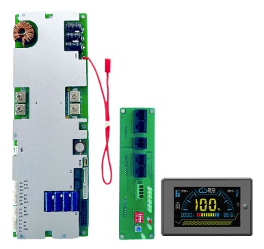
FYI, JK has released a new BMS for inverters and the CAN communication port supports several inverters and protocols like Pylontech.
It's very recent, the firmware is not yet very mature but it can be updated.


Andy's first videos are not encouraging but the comments I read afterwards speak of a new firmware which corrects some of the problems without being perfect. It's undoubtedly a nice product, hoping that JK continues to improve the firmware.

Andy should also talk about a new BMS made in Australia with a good price and that would be great. It will be in the videos to come. Wait and see.
 
  • Like
Reactions: hgg

diy solar

diy solar
Back
Top