uksa007
Solar Enthusiast
- Joined
- May 26, 2022
- Messages
- 239
The same way used to upload the code onto the ESP32.Where should I run this command ?


The same way used to upload the code onto the ESP32.Where should I run this command ?
Hello, there's a compilation error with ESPHome 2023.4.0, because of this modification :
UART ids
Due to uart0 / uart1 / uart2 being defined in some of the platform code ESPHome uses, ESPHome will now disallow these ids from being used in the config. You can simply change them to uart_0 to continue using.
Maybe you should change the examples files ?
 github.com
Worked ok for me ??Updated code, can you please test and let me know if this resolves your issues?
- V1.13.1 24/4/23 Fix compile issues with new version of ESPhome 2023.4.0, set rebulk offset to 2.5

esphome-jk-bms-can/esp32-example-can.yaml at main · Uksa007/esphome-jk-bms-can
ESPHome component to monitor a Jikong Battery Management System (JK-BMS) via RS485 or BLE, CAN bus Goodwe/Pylon - Uksa007/esphome-jk-bms-can
I don't understand this part, I uploaded the code through Home assistant ESP implementation ?The same way used to upload the code onto the ESP32.

I use ESPhome on windows, so that how I get logs.Hello i'm still having disconnection issues, but I can't figure out if it's wifi related or anything else.
I don't understand this part, I uploaded the code through Home assistant ESP implementation ?
If I activate the logs in the YAML there's really a lot of things reported so it's difficult to diagnose

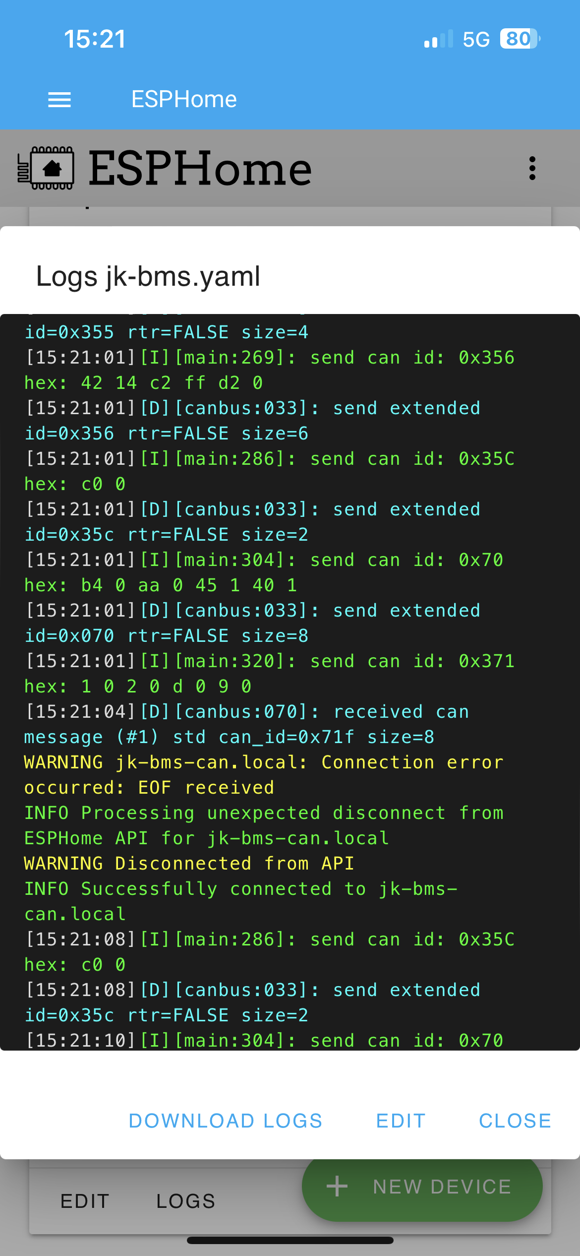
Hopefully it will give me an idea of what's going on.Yes that's how I do but when I loose connection, there's no logs anymore ?
Any chance you can download the logs and attach them here?Here’s what I fetched
I have a repeater with the same ssid as the router and the esp has connected to the router instead of the repeater. I have specified the bssid instead the ssid and it works fineAny chance you can download the logs and attach them here?
What is the value of "Uptime Human Readable" sensor in Home Assistant or in the logs?
It looks like the ESP disconnected from WiFi, what is its WiFi signal like?
Try to move it closer to the access point or try changing the channel on the access point
thanks for doing this. What happens when one of the slaves or master stops accepting charge such as from a high cell voltage?Multi BMS Alpha code now released.
Update: Alpha V2.16 more info here
I completed and implement the initial design, the data is now combined from the slaves as per the design.
I have made many improvements and made the code more robust, see the above link for more info.
Future plans include adding Multi BMS support for JBD/Overkill so you can mix and match BMS in the one larger pack.
As per the design:thanks for doing this. What happens when one of the slaves or master stops accepting charge such as from a high cell voltage?
It's on my radar but not something that has many requests or any Patreon supporters, so I haven't progressed with it.Hi! Thanks for all the great work! Do you have plans to support RS485 pylontech protocol with JK BMS for supported inverters in the future?
Thanks for the reply. I really hope one day you will be able to make/release it as all of the voltronic inverters don’t support pylontech over CAN.It's on my radar but not something that has many requests or any Patreon supporters, so I haven't progressed with it.