diy solar

diy solar

JK BMS CAN bus comms now possible for inverters that support Goodwe and Pylontech batteries

Hi Uksa007, i have now connected wire as above (2-5 and 7-4) and set the correct dip switches 2 and 3 ON; Battery is not seen on SofarSolar graphic on inverter panel. i tested DC outlet from inverter 3.5V; then connected DC power cable and i have 56,7V, those volts come from battery but inverter is not charging battery; Event list : ID52 BMS disconnected and ID 36 Meter com Fault
I assume you have correctly configured the inverter for CAN bus battery, maybe try restarting the inverter, disconnect mains and battery.
Apart from the above, sorry I'm out of ideas, you will need to contact the battery and inverter manufacturers and see if they have any further advice.
 
Hi,

The BMS side looks correct, please see here for more info https://github.com/Uksa007/esphome-jk-bms-can#schematics
1m for the TLL cable is probably getting a bit long I would recommend keeping it under 30cm or use the RS485 modules.

The TJA1050 I normally use:
can_tx_pin: GPIO23
can_rx_pin: GPIO22

Regards.
Thank you, can you confirm that on both sides, TX and RX are crossed between ESP32 and tranceivers ?
 
I assume you have correctly configured the inverter for CAN bus battery, maybe try restarting the inverter, disconnect mains and battery.
Apart from the above, sorry I'm out of ideas, you will need to contact the battery and inverter manufacturers and see if they have any further advice.
hi, i have olready contact providers, they dont answer; i'll ty to test continuity the cable and make another cable
 
Thank you, can you confirm that on both sides, TX and RX are crossed between ESP32 and tranceivers ?
As per the code only the JK-BMS are crossed, CAN is TX to TX etc.

# ESP32 Serial port pins:
# GPIO pins your CAN bus transceiver(TJA1050) is connected to the ESP, note! TX->TX and RX->RX.
can_tx_pin: GPIO23
can_rx_pin: GPIO22
# GPIO pins your JK-BMS RS485(TTL) is connected to the ESP TX->RX and RX->TX.
tx_pin: GPIO17
rx_pin: GPIO16
rx_timeout: 150ms
# ----------------------
 
hi, i have olready contact providers, they dont answer; i'll ty to test continuity the cable and make another cable
Try emailing: tech.au@alpha-ess.com or Contact whoever you purchased the battery from and ask for assistance, maybe there is new/different firmware needed?
 
I assume you have correctly configured the inverter for CAN bus battery, maybe try restarting the inverter, disconnect mains and battery.
Apart from the above, sorry I'm out of ideas, you will need to contact the battery and inverter manufacturers and see if they have any further advice.
I have updated firmware to 3.60 and the battery appear on graphic but i have no ct power no grid power no DC power, i wait for the sun goes up and see what to do, i had also sofarsolar europe who told me china will contact me, i 'll tell you tks
 
As per the code only the JK-BMS are crossed, CAN is TX to TX etc.

# ESP32 Serial port pins:
# GPIO pins your CAN bus transceiver(TJA1050) is connected to the ESP, note! TX->TX and RX->RX.
can_tx_pin: GPIO23
can_rx_pin: GPIO22
# GPIO pins your JK-BMS RS485(TTL) is connected to the ESP TX->RX and RX->TX.
tx_pin: GPIO17
rx_pin: GPIO16
rx_timeout: 150ms
# ----------------------
Thanks I did not looked at the code, sorry :(

Maybe the schematic on the github page needs to specify the pinout / colors?

Code:
              RS485-TTL                  RS485             RS485-TTL               RS232-TTL                CAN BUS
┌──────────┐            ┌───────────┐           ┌────────┐           ┌─────────┐             ┌─────────┐              ┌──────────┐
│          │<--- TX --->│Y    JK   Y│<A------A+>│        │<TX-----RX>│16     23│<TX-------TX>|         |              |          |
│  JK-BMS  │<--- RX --->│W  RS485  W│<B------B->│ RS485  │<RX-----TX>│17     22│<RX--4K7--RX>| TJA1050 |<---CAN H --->| Inverter |
│          │<--- GND -->│B Adaptor B│<---GND--->│To 3.3V │<---GND--->|         |<----GND---->|   CAN   |<---CAN L --->|          |
│          │<--Bat V -->│R          │           │        │<---3.3V-->|  ESP32  |<----5 V---->|         |              |          |
└──────────┘            └───────────┘           └────────┘           └─────────┘             └─────────┘              └──────────┘
 
Hello, I can now confirm it works fine (had to remove the "latest" in the framework section to compile ESP Home.)

If you want to add to the compatibility list I have JK BMS JK-BD6A17S8P with Sofar Solar Hybrid Inverter HYD-5000-ES (Firmware V3.60) in Pylon mode (US5000)

Thanks a lot :)
 
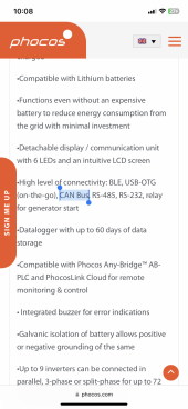
I have a phocos 5kw hybrid inverter and I have ordered the jk B1A20S15P but I don’t know if this bms has CAN/BUS. Will this work on my configuration? Thanks

Ps: my inverter supports PylonTech. I have 16s lifepo4 cells
 
I have a phocos 5kw hybrid inverter and I have ordered the jk B1A20S15P but I don’t know if this bms has CAN/BUS. Will this work on my configuration? Thanks

Ps: my inverter supports PylonTech. I have 16s lifepo4 cells
Not sure, your inverter will need to support CAN bus, it seems to use RS485 for pylon.

It seems similar to other inverters that support CAN, can you set the battery type to 00?
 
Not sure, your inverter will need to support CAN bus, it seems to use RS485 for pylon.

It seems similar to other inverters that support CAN, can you set the battery type to 00?
This inverter supports CAN, I don’t know about the BMS i ordered (jk bms).

Check page 27-28 on my inverter manual to see supported battery protocols

No there’s no 00 option in battery menus
 
There is no mention of any Batteries that use CAN, Battery type 05 is RS485.
Check with the manufacturer but it looks to me like there is no CAN support.
IMG_8478.png
Check this one out. Phocos, does updates frequently and they have their own FW even thought it looks its just a rebranded inverter
 
Last edited:
Oh i just remembered. They have their own battery and it seems it connects to their communication device called any-bridge and this one actually has a CAN port. I own it, maybe it could work that way ;)
 
Back
Top