


You are using an out of date browser. It may not display this or other websites correctly.
You should upgrade or use an alternative browser.
You should upgrade or use an alternative browser.
Warpverter
- Thread starter Nobodybusiness
- Start date
A separate system could monitor battery charge and operate a contactor to disconnect the grid tie inverter AC.Ok so it's a control algorithm problem to solve. I was wondering if warpverter power stage topology is capable of operation in that mode.
Warpspeed
Solar Wizard
I have been playing around with these ideas for over forty years. Its all now finally come together, and its very satisfying seeing others successfully build this type of inverter. Unless you are aiming for about 5Kw or more, pwm is a much simpler and more sensible approach.I've now built several inverters. But when I first got started, one of the avenues I researched was the Warpverter. I am still very impressed by the ingenuity of the design. Ultimately I went the standard PWM route due to well-worn simplicity and not desiring to wind 4 transformers! It took a while to understand the theory of the Warpverter and although I haven't built one, it is an edifying exercise.
Its at the higher power levels, that makes home brew pwm very difficult.
It can be done, and has been done, but its not so easy getting the reliability.
Winding four transformers is a huge undertaking, and not to be taken lightly.
But if serious power is your goal, a Warpverter is likely to cause you much less long term grief.
Its a lot of work, but you only have to do it once !
Last edited:
Warpspeed
Solar Wizard
Yes.Ok so it's a control algorithm problem to solve. I was wondering if warpverter power stage topology is capable of operation in that mode.
PWM or Warpverter is just a means of turning dc into ac. Two very different types of power stages.
Its how the process is controlled, in other words a software algorithm problem or what generates and synchronizes the inverter to the grid.
Hedges
I See Electromagnetic Fields!
- Joined
- Mar 28, 2020
- Messages
- 21,483
A separate system could monitor battery charge and operate a contactor to disconnect the grid tie inverter AC.
Just shift frequency of timebase up and down to control frequency-watts GT PV and regulate battery voltage and charge rate.
I know this is all a rather difficult concept to get your head around to begin with, but please try to bear with me....
Clear as mud for some, I'm sure. But I follow it completely.
Considering I've dealt with transformers a bit, also transistor amplifiers.
Check out my threads on transformers and 3-phase. The issues of saturation are quite relevant.
Also, not detailed much here, is my measurement of BH curve and building "Chan" model simulations. Different core materials and annealing relate to the different curves.
Hedges
I See Electromagnetic Fields!
- Joined
- Mar 28, 2020
- Messages
- 21,483
Yes, that is it EXACTLY.
Single phase?
Should be able to put 2 secondary windings on each transformer. That will give 120/240V split-phase. Full wattage available as surge for 240V or for either 120V phase. Continuous if secondary windings of suitable gauge.
I can see why it doesn't work parallel to another source like grid. No adjustable voltage or current. Best you could do is phase shift between charge/discharge to regulate average current, but seems quite problematic.
Does AC Vpeak and Vrms vary as battery voltage varies? Or do you change timing and number of steps to compensate?
I’m glad this has it’s own thread, and that there are a few here that appreciate the design. I have followed this idea for a long time across various forums, and it has often been misunderstood or dismissed.
I feel this is a good reflection of the quality of the membership base of this forum.
I feel this is a good reflection of the quality of the membership base of this forum.
Warpspeed
Solar Wizard
How the voltage regulation works.
The transformers are wound with primaries to suit the lowest incoming dc voltage.
At the lowest design voltage, the transformers are switched to produce the full 81 step voltage range and nominal ac output voltage.
Because the transformer ratios are fixed, increasing the dc voltage would produce a corresponding increase in ac output voltage.
My own Warpverter works between 90v and 180v incoming dc voltage. Yours might be any 2:1 dc voltage range.
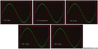
The waveforms shown below are with only three inverters running which produces 27 steps.
With fewer steps its much easier to see the changes that occur.
The fourth inverter produces such a smooth sine wave its very difficult to see anything happening.
At minimum dc input voltage of 90v you can see the full 27 steps.
If the input voltage is increased to 95v, notice the top step right at the peak has become slightly narrower.
In fact all of the steps are made slightly narrower, but its most noticeable right at the peak.
This overall change in the waveform corrects for the 5v dc increase, producing the same nominal rms ac output voltage.
If we keep slowly increasing the incoming dc voltage, eventually the top step becomes narrower and narrower, finally disappearing, and we have fewer steps peak to peak. This provides very fine output voltage control, and we can have a regulated output voltage over a very wide 2:1 change in dc input voltage.
The change in waveshape is produced by jumping between lookup tables in ROM.
The jump always occurs right at a zero crossing, so large output voltage corrections can be made without causing any discontinuity in the sine wave. There are 256 different lookup tables that cover the 2:1 dc input voltage range.
What determines which lookup table to use is a measurement of the incoming dc voltage. That is measured 25 times each second, and the ac output voltage is fully corrected every second mains cycle right at the zero crossing. This system does not require any voltage feedback from the output of the inverter. Its very fast acting compared to feedback, and it can never become unstable in the way feedback sometimes can.
The only disadvantage is that due to slight voltage droop with increasing load in the transformers, and voltage drop in the IGBTs, the ac output voltage does fall slightly with increasing load. In my own inverter its about a ten volt drop at 5Kw of load, compared to zero load.
The grid does that anyway, and its never been a problem here.
That can be corrected by measuring the DC input current to the inverter and using that to modify which lookup table is selected beyond what the incoming voltage measurement dictates. I have tested the idea and it works as expected, but have not bothered to build another control board to incorporate it into my own inverter. Other Warpverter builders are using the current measuring modification and are very pleased with it.
This voltage regulation all works backwards when back charging a Warpverter from a grid tie inverter. It still regulates the ac voltage, preventing it from rising when the grid tie inverter is back feeding.
Here are some waveforms showing the effect of different dc input voltages on the ac output with only three inverters running.
The oscilloscope is set for 100v per division.
Ac output voltage is held pretty constant even though the vertical height of each step increases in proportion with the increase in dc input voltage.
The transformers are wound with primaries to suit the lowest incoming dc voltage.
At the lowest design voltage, the transformers are switched to produce the full 81 step voltage range and nominal ac output voltage.
Because the transformer ratios are fixed, increasing the dc voltage would produce a corresponding increase in ac output voltage.
My own Warpverter works between 90v and 180v incoming dc voltage. Yours might be any 2:1 dc voltage range.
The waveforms shown below are with only three inverters running which produces 27 steps.
With fewer steps its much easier to see the changes that occur.
The fourth inverter produces such a smooth sine wave its very difficult to see anything happening.
At minimum dc input voltage of 90v you can see the full 27 steps.
If the input voltage is increased to 95v, notice the top step right at the peak has become slightly narrower.
In fact all of the steps are made slightly narrower, but its most noticeable right at the peak.
This overall change in the waveform corrects for the 5v dc increase, producing the same nominal rms ac output voltage.
If we keep slowly increasing the incoming dc voltage, eventually the top step becomes narrower and narrower, finally disappearing, and we have fewer steps peak to peak. This provides very fine output voltage control, and we can have a regulated output voltage over a very wide 2:1 change in dc input voltage.
The change in waveshape is produced by jumping between lookup tables in ROM.
The jump always occurs right at a zero crossing, so large output voltage corrections can be made without causing any discontinuity in the sine wave. There are 256 different lookup tables that cover the 2:1 dc input voltage range.
What determines which lookup table to use is a measurement of the incoming dc voltage. That is measured 25 times each second, and the ac output voltage is fully corrected every second mains cycle right at the zero crossing. This system does not require any voltage feedback from the output of the inverter. Its very fast acting compared to feedback, and it can never become unstable in the way feedback sometimes can.
The only disadvantage is that due to slight voltage droop with increasing load in the transformers, and voltage drop in the IGBTs, the ac output voltage does fall slightly with increasing load. In my own inverter its about a ten volt drop at 5Kw of load, compared to zero load.
The grid does that anyway, and its never been a problem here.
That can be corrected by measuring the DC input current to the inverter and using that to modify which lookup table is selected beyond what the incoming voltage measurement dictates. I have tested the idea and it works as expected, but have not bothered to build another control board to incorporate it into my own inverter. Other Warpverter builders are using the current measuring modification and are very pleased with it.
This voltage regulation all works backwards when back charging a Warpverter from a grid tie inverter. It still regulates the ac voltage, preventing it from rising when the grid tie inverter is back feeding.
Here are some waveforms showing the effect of different dc input voltages on the ac output with only three inverters running.
The oscilloscope is set for 100v per division.
Ac output voltage is held pretty constant even though the vertical height of each step increases in proportion with the increase in dc input voltage.
Attachments
Last edited:
The heart of the Warpverter is a done deal. I'm sure that could be added, but as an off-the-shelf unit, it might be easier as a separate control scheme.Just shift frequency of timebase up and down to control frequency-watts GT PV and regulate battery voltage and charge rate.
How many Kbytes total for entire ROM ?There are 256 different lookup tables that cover the 2:1 dc input voltage range.
Warpspeed
Solar Wizard
Each lookup table is 1K.
256K total
256K total
Re: back charging. I have a LF off grid inverter with a cheap fleabay grid tie inverter on the output. This plugs into a smart plug and I use Home Assistant to turn it off at a set battery voltage and then on again at a lower voltage. Been working great for some months now.No. This is not a grid tie inverter, there is no way to synchronise a Warpverter to the grid.
Its intended for off grid applications only.
However when running off grid, you can couple up a grid tie inverter to a Warpverter to back charge a battery through the Warpverter.
The Warpverter then becomes the grid, as far as the grid tie inverter goes.
The only disadvantage is that you could overcharge the battery doing that, as the grid tie inverter has no way of knowing when the battery is full.
Warpspeed
Solar Wizard
I started out using microcontrollers, but quickly realized that the only way to make the whole process fast enough was with lookup tables.Very cool design. Essentially a hardware based state machine.
Real time number crunching is just not practical. I went through using dual port rams, all kinds of things.
Finally went to pure hardware, its quite simple really.
Just cycle through 1K of ROM at 50Hz (or 60Hz) and latch that onto the output.
The bit patterns stored in ROM are direct on/off gate drive data. Eight latched output bits switch eight half bridges through opto isolators, there is no data manipulation required.
Use a very accurate and stable dual slope 12 bit analog to digital converter to select one of the 256 lookup tables.
The dual slope integrating A/D averages out any ripple or noise on the battery, which can be considerable if for example there are solar controllers or other stuff connected to the battery.
Last edited:
Do you store data bits for full sine wave cycle or just 1/4 of it and flip/invert in hardware? I would like to look at detailed implementation of the EEPROM. Using parallel data output of ADC and driving address select bits of EEPROM is very clever. I would probably just have an 8 bit microcontroller in the middle of it all running assembly code.
RCinFLA
Solar Wizard
- Joined
- Jun 21, 2020
- Messages
- 3,566
Original 1994 Trace patent for the original SW series inverters.
Low leakage inductance, tight coupling transformers allow each transformer to produce three discrete voltages; +v, 0, -v. Three transformers with three discrete voltages allows up to 3^3 = 27 voltage steps. Less steps typically used to regulate ratio between variable battery voltage/AC output voltage and wire losses under load current. Most number of steps are used when battery voltage is lowest and AC voltage required to match grid is highest. Lowest number (rattiest sinewave) is used when battery is at highest voltage with grid matching at low AC voltage.
It is important that the switching duty cycle on each transformer always maintain 50% duty cycle (equal pos and neg voltage periods) to prevent magnetically biasing the transformer core.
Extra complexity and additional losses of four transformers stack is not really worth the reduced discrete step voltages on AC output over a three stacked transformer design. Four stacked transformer would theoretically give up to 3^4 = 81 discrete steps in AC output sinewave approximation, but again, less steps are used most of the time for regulating variable battery to AC output voltage ratio.
When grid drops out and inverter takes over, I can barely hear an increase in 'buzz' from the ceiling fan in quiet bedroom.
Attachments
Last edited:
Warpspeed
Solar Wizard
A whole 360 degree ac cycle spread across 1K.Do you store data bits for full sine wave cycle or just 1/4 of it and flip/invert in hardware? I would like to look at detailed implementation of the EEPROM. Using parallel data output of ADC and driving address select bits of EEPROM is very clever. I would probably just have an 8 bit microcontroller in the middle of it all running assembly code.
There is no data manipulation, the whole thing is just a ROM directly driving the IGBT switching bridges through a latch.
Over many years the greatest challenge has been to make it as simple as possible with as few ordinary easily obtainable parts as possible.
Warpspeed
Solar Wizard
I started long before 1994 developing the idea quite independently.Original 1994 Trace patent for the original SW series inverters.
View attachment 171126View attachment 171128View attachment 171127
I was aware of the Trace, but have never actually seen one, and until recently knew very little about them.
They are EXCELLENT inverters and have a reputation for top notch reliability.
There are significant differences, its not just that the Warpverter has the extra inverter.
The Warpverter has feed forward voltage regulation, the Trace probably uses the more usual voltage feedback.
Not worried about any patent. I am not in business, and not trying to sell anything to anyone.
Its all free and open source knowledge for anyone that might be interested in home brewing something for themselves.
Last edited:
There is information somewhere on how someone can duplicate what you built?Its all free and open source knowledge for anyone that might be interested in home brewing something for themselves.
Warpspeed
Solar Wizard
Right here hopefully, if there is enough interest to keep the thread going.There is information somewhere on how someone can duplicate what you built?
Warpspeed
Solar Wizard
Sadly, that seems to be very true.This is a forum of magic boxes and plug-and-play. High power homemade electronics and hand wound transformers don't seem to have much traction 'round these parts.
I have presented several unique and proven to work design ideas here, only to be met with zero interest.
You’ve obviously missed threads like BiduleOhm’s DIY BMS.This is a forum of magic boxes and plug-and-play. High power homemade electronics and hand wound transformers don't seem to have much traction 'round these parts.
There are a few minds around here that have no problems understanding the Warpverter and i’m sure anyone with the time and inclination to have a crack at building one will get all the support they need.
I am interested in building my own 48V inverter and I already have 27V > 120/240V 6kVA transformer for it (out of XW6848). I really like this design but I don't want to rewind the primary of this transformer. If I get access to more transformers I will try it!
Hedges
I See Electromagnetic Fields!
- Joined
- Mar 28, 2020
- Messages
- 21,483
Sadly, that seems to be very true.
I have presented several unique and proven to work design ideas here, only to be met with zero interest.
I certainly find them interesting, but already having some 68kW of Sunny Island and 165kW of Sunny Boy & TriPower, I think I'm good for the moment.
... and hand wound transformers don't seem to have much traction 'round these parts.
Been there, done that, handed it off to manufacturing. (RF, not power)
But then, I'm "special"
As I proposed, I think your transformer could easily be modified for split-phase.
I also think, using something like 400V or so HV battery bank and various voltage 3-phase transformers, a 3-phase system could be made.
480:480 isolation, 480:240, 480:208, 600:xxx, etc.
Isolate the Wye secondary windings so those from each transformer can be connected in series.
Last edited:
Similar threads
- Replies
- 26
- Views
- 2K
- Replies
- 10
- Views
- 487
- Replies
- 11
- Views
- 426
- Replies
- 1
- Views
- 406