diy solar

diy solar

Warpverter

35W idle sounds great for a 15kW inverter, normal for 5kW.
Will be interesting when you power a 15kW air compressor with 75kW surge. But not many single phase loads that big.

Performance with inductive/capacitive loads that have out of phase current, and other poor PF loads like LED lights and non PFC VFD.

If the situation that blows of FETs can be monitored, like overlap or non-overlap of gate signals, can you monitor that and back off to adjust prior to failure rather than fixing after failure?

Is insufficient overlap damaging, tries to block inductive kick rather than freewheel? If so does the architecture allow a diode to do the switching automatically, just with more loss?
 
Thirty five watts of idling power for a 15Kw rated inverter is quite an achievement.
My idling power is the same 35w, but for only a 5Kw rating.

When I started out, I was scared as well.
Its a natural reaction for something that has consumed a lot of time, effort, and money to put together, and might explode at any moment.
As time went on, I gained more and more confidence in it.
After six plus years of continuous operation, it has never missed a beat.
I have tripped the 20amp thermal/magnetic breaker on the output many times, but the inverter just kept running every time.

Performance with inductive/capacitive loads that have out of phase current, and other poor PF loads like LED lights and non PFC VFD.

If the situation that blows of FETs can be monitored, like overlap or non-overlap of gate signals, can you monitor that and back off to adjust prior to failure rather than fixing after failure?

Is insufficient overlap damaging, tries to block inductive kick rather than freewheel? If so does the architecture allow a diode to do the switching automatically, just with more loss?

Switching bridges are fully inherently protected from noisy or scrambled drive data and shoot through, by design.
Mosfets (and IGBTs) have inverse diodes that carry reactive current during dead time.
Only lethal susceptibility is if the clock oscillator stops or is slow to start up. That can leave diagonal mosfets turned continually on.
Crystal oscillator uses a commercial oscillator module, guaranteed to run between 2v and 6v. Frequency stability of these is pretty good too.
Klaus is the only person that has had reliability problems, and those have been both serious and ongoing.
 
Will be interesting when you power a 15kW air compressor with 75kW surge. But not many single phase loads that big.

Haha, yeah it might take me a while to get to that stage. I had enough trouble pulling the trigger on my 2kW compressor.

Performance with inductive/capacitive loads that have out of phase current, and other poor PF loads like LED lights and non PFC VFD.

Good comment, I really need to start trying those sorts of loads. I didn't realise quite how hard it is to test something like this until I started running around looking for things I can plug in.

When I started out, I was scared as well.
Its a natural reaction for something that has consumed a lot of time, effort, and money to put together, and might explode at any moment.

Yes, exactly right. I think reading all those threads on the back shed where guys had failure after failure and seeing just how demoralising it can be ... and also the fact of the years of time and money invested in the project ... if it doesn't work and can't keep it working ... what a failure!!!

Certainly the longer it runs and the more load I apply without drama, the more my confidence is growing.

If the situation that blows of FETs can be monitored, like overlap or non-overlap of gate signals, can you monitor that and back off to adjust prior to failure rather than fixing after failure?

I'm really glad Tony is here to answer these sort of questions ... I'm an electronics tech ... I'm definitely no EE.

I am hopeful that the fet blowing issue was simply because of the dead-time setting. That all happened in the first two days of firing up ... and it had only been running a 15 watt load until then. Although I have to admit that I had forgotten to solder 3 legs of an optocoupler on that bridge ... so that may have been the cause for the very first one. Bit embarrassing. :giggle:

I did certainly monitor the switching to see that the timing definitely increased to the 2.3uS ... so I don't think it could change. I suppose I could add more ... but while it's behaving I will keep my fingers crossed. I suppose in industry it would be constantly tested to destruction ... but I'm a little adverse to loud bangs and bright flashes ... and the time needed to repair the damage. 😁


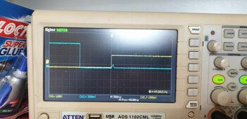
This image is of the inputs to the optocouplers on one of the large tx half-bridges. A quite definite dead-time there ~2.3uS

Dead-time.jpg


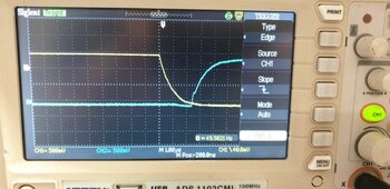
This is on the gate drive ... so maybe it should be a little wider.

Maybe I need to watch while I stick on some horrible loads. ???

Dead-time2.jpg
 
I am only driving single large individual IGBTs which is not too difficult, especially at only 50Hz in the largest inverter.
No dead time capacitor fitted, gives about 60nS dead time. A 1nF capacitor about 200nS. A 10nF capacitor about 2.4uS.

I never tried anything larger than that, but 100nF might produce about 24uS as a guess.
What I ended up using was 1nF dead time capacitors in the two smaller inverters which use either mosfets or small IGBTs.
In the two larger inverters using giant IGBT power blocks, 10nF dead time capacitors.

Driving multiple paralleled gates of large mosfets takes a lot more grunt to do really fast, but we don't really need high switching speed at 50Hz.
So just accept that, and give it plenty of extra dead time, and it will be fine.

Its sobering to realise that comparing PWM switching at 20 Khz to switching at only 50 Hz is x 400 faster.
Its about the same speed differential as comparing something flying at the speed of sound, to a guy pushing a wheelbarrow.

So don't fret about winding dead time out to several or even tens of microseconds.
Not that it needs that much, but it would certainly be practical to do so.

Idling power is a pretty good indication that all is well with dead time.
If increasing dead time does not change idling power, you already have enough.
If more dead time does bring down idling power, perhaps try it again with just a bit more.
 
Last edited:
Shoot through of 200ns can occur on start up with the OzInverter with a poor switch on proceedure and can give contact bounce on the IFB or TFB error condition.

With the Warpverter, Tony has cleverly removed shoot through possibility by his design.

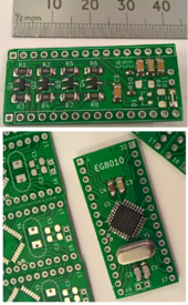
I am now working with 'GASPO's 'anti shoot through daughter board' for our common 8010 SMD PWM chip, as a standard plug in replacement replacement for our daughter board on the OzInverter control board.

Thanks 'Peter' for your help.

GasposPCBsentToMe.png.
 
Last edited:
Most inverters use multiple power supply rails, +5v, +12v, with usually an isolated gate driver dc supply as well.
Now the problem is, these may not all behave themselves during power up, power down, or brownout.
Decoupling capacitors store energy and can change the dynamics of the various dc supply rails in unfortunate ways.
Its possible sometimes, for a spike or a glitch, which may not be repeatable to cause a momentary catastrophic shoot through event.

Inverter designers have nightmares about these kinds of issues (or at least they should).
Any kind of microcontroller can introduce a few extra unknowns into all this as well, its the main reason why I eventually went to a very simple no frills all hardware design.

My solution to shoot through was to use opto isolated gate driver chips, and connect the LEDs in inverse parallel. There is simply no way both LEDs can ever both be on together. So regardless of whatever else happens, shoot through should never be able to occur in a Warpverter.
The simplest solutions are very often the best.
 
My Warpverter has now been hooked up to the house and workshop ... since yesterday morning ... and has been running happily ever since.

While it had run up 373kWh of testing, it was still a bit nerve wracking to let it loose on all our household electrics ... and with five of us in the house there's a constant changing of demand on it.

Fortunately it's been smooth running so far and I'm a bit in awe of the fact that we've been able to switch off the mains and are running from the forklift battery. The solar charge controller kept the battery supplied with more than we were using most of the day ... though I do need to fit the remaining panels to be sure of a good regular charge.

We have two lots of 12 x 275w panels set up 3s4p running into two mppt controllers ... and need to fit the other 24 x 250w panels in the same way to the other two mppt units. 6.6kW so far with another 6kW to go.

The only change I noticed was while checking it just before I went up to the house for lunch ... and the normally quiet buzz of the transformers turned into a rattly warbly buzz which I had not heard before. Total draw at the time was just over 2000 watts ... though it stopped and went back to normal fairly quickly.

When I got to the house I heard a microwave start up, so that seems to make it rattle a bit for some reason. Maybe tomorrow, I'll monitor the ac waveform and try out the microwave again.

I scored some 95mm cable and some lugs to make new battery cables, so that's a job for the weekend. Interestingly, the forklift tech said not to crimp the battery ends but to simply solder them into the ends. Mmmm. :)

And of course I need to get on with making the covers for the devices. Gotta keep the dirt and dust out as well as any prying fingers.

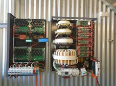
Mppt's and Warpverter.jpg
 
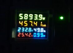
We had a pretty warm day here today around 38C and 41C forecast for the next three days. So the Warpverter had a pretty decent workout with pool pumps, air con, vacuuming, microwave and eventually oven as well. Highest load was 5,893w and didn't seem an issue at all.

Unloaded the inverter sits around 241.5v When I first set it up I set it to 240.0v ... but since running on the forklift battery it's a bit higher.

Considering it doesn't have a voltage feedback system it still manages to stay within a reasonable range. I took a heap of random readings today and the lowest I saw was 232.7v with a load of 5,782w

Some of the other readings ... 3,331w 237.0v ... 4,042w 235.4v ... 2,389w 238v ... 3,974w 234.9v ... 4,200w 236.2v ... 3,989w 236.4v ... 670w 240.3v

Was a pretty big day for it and so far today has generated 34.89 kWh. Still 90 mins to go. 😁 The big toroid got up to 42C but then the ambient in the shed was high 30's anyway. The Warpverter heatsink seems to stay pretty much at ambient anyway.

Because I haven't fitted the fan to the inverter yet, I aimed a pedestal fan at both the charge controller and inverter to make sure they didn't get too hot. Slowly clocking up some hours.

Power Monitor.jpg
 
Here in Melbourne, we get the very same hot days about a day behind Adelaide.

Your voltage regulation sounds about the same as my own, up and down by a few volts, but never by enough to be of any real concern.
The grid here varies by a similar amount anyway. There is no real requirement for absolutely perfect voltage regulation, and the Warpverter seems to do quite well despite not having any voltage feedback taken from the output.

I fitted a large centrifugal blower fan to my heatsink, and set the controller to start it up at 45C and off at 40C, as far as I know its never come on over the last six years of continuous operation. These three hot days in a row will be a good test.

Temperature rise is a pretty good indicator of efficiency at the higher power levels, and your Warpverter sounds like its doing just fine.
 
Just an update on my Warpverter build.

I started to run out of battery a few times after getting a bit carried away running everything I could on all this "free energy" ... so I fitted the extra panels I had planned and hooked them up to the other two mppt controllers. So now 48 panels set up in four 3kw arrays. Has made a huge difference to the charging rate and kept the battery very happy.

Over the weekend we had some nice sun despite being half way through autumn ... and with the chargers throttling right back I decided to hook up one of the under floor heater circuits (3,000W) to see how well it performed ... and to use some of the power we were leaving behind. We've been here 10 years and the previous owners had fitted it but never hooked it up because they discovered the wiring and supply could not handle the additional load. Ouch!

The inverter seemed to handle it okay and so today being very similar weather, I ran it again. When I checked, the mppts were still throttling back so I decided to really try it out and hooked in a second heater ... so 6,000 watts extra on top of our normal usage.

For a while there the chargers were pumping out 140 amps and the battery was still getting 18-20 amps of charge.

With the 6,500w load the Warpverter output was dropping from its normal 240v to 230.8v ... and way up in the house at the heater points it was down to 222v. There's 140 metres of cable between the two, so have to expect some drop I guess.

I ran them both for 4 and a half hours and then switched off one when the charge rate started to drop ... then ran that one for another hour. So 4 and a half hours at 6,500 watts and occasional hikes to nearly 8,000. What really surprises me is that the electronics never gets more than a few degrees above ambient and the heatsink is essentially at ambient.

The two larger transformers did start to warm up and got to around 50C until I turned on a pedestal fan to give them some air which brought them down into the low 40's. I really need to fit the barrel fan I have prepared to cool both the toroids and the heatsink.

The unit has clocked up 1,225kWh so far, so I'm very happy with how it is going. I noticed the meter reader here last week, so hopefully that will be our last ever big electricity bill. There's still a daily supply charge of $1.08 plus any extra we might use if we have to charge the battery overnight etc ... but for the first time ever, I might start looking forward to receiving them.
What is the the absolute maximum you can pull from your warpverter?
 
What is the the absolute maximum you can pull from your warpverter?

It's theoretically 15kW. I've got to just over halfway a few times and this was certainly the longest run at this level ... it just requires courage or bravado that I struggle to find. The longer it goes the more confident I am getting ... but it's still nervewracking. :)
 
With the 6,500w load the Warpverter output was dropping from its normal 240v to 230.8v ... and way up in the house at the heater points it was down to 222v. There's 140 metres of cable between the two, so have to expect some drop I guess.
The way around that would be to fit the optional feed forward current correction.
What that does, it uses a Hall current sensor in the dc supply to the Warpverter. The increase in inverter load is sensed, and the 2.5v voltage reference in the Warpverter is slightly modified (raised) by a few millivolts with increasing inverter load.
The Warpverter is fooled into thinking the incoming dc voltage has fallen slightly, so it jacks up the ac output voltage to compensate for increasing inverter load.

Very few extra components are required, a high current Hall sensor, a potentiometer, and one extra resistor. If you use one of Klaus's control boards it has the extra components already there, and it will plug straight into your Warpverter. Or you could add the extra components to the control board you already have. Klaus has offered to supply a free working circuit board, so its worth a try.

The pot can be tweaked to adjust the amount of of output voltage correction with increasing load, even to the point where ac output voltage rises with increasing inverter load. It should then be possible to correct the voltage at the house, at the remote end of your long cable run.
This works especially well with short duration surge loads, removing the worst of the voltage dips, and there will be no instability at any load correction setting.

If you ever eventually couple up a grid tie inverter to your Warpverter, this load correction works in reverse. It prevents the ac voltage from rising excessively when you pump ac current back into the Warpverter.
It's theoretically 15kW. I've got to just over halfway a few times and this was certainly the longest run at this level ... it just requires courage or bravado that I struggle to find. The longer it goes the more confident I am getting ... but it's still nervewracking. :)
Ah ! Home brewers anxiety.
Know that all too well.
I think we have all gone through that stage at the beginning.
A kind of euphoria mixed with absolute terror.


Like Reply

Report
 
Last edited:
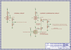
Here is the schematic of how the Warpverter load compensation works.
Original circuit on the left generates a constant +2.0v reference voltage for the analog to digital voltmeter chip on the control board.

Modified circuit on the right uses a Hall current sensor to modify the 2.0v reference voltage, such that a rising inverter load jacks up the ac inverter output voltage by the required amount to correct for voltage droop with increasing inverter load.
Extra components required to do this are only three, the Hall sensor, one resistor, and a potentiometer, and the values may need to be changed to get the desired amount of voltage droop correction.

I have assumed here that your 15Kw 48v Warpverter draws about 340 amps at 15Kw ?
The 500 amp rated Hall device outputs +2.5v at zero inverter load, and about +3.86v at 340 amps, and +4.5v at 500 amps.
A 1K pot adjusts the available correction from zero to a maximum of roughly +10% voltage increase at 340 amps of load with the values shown.
With the pot set in the middle, there will be about 5% inverter output voltage increase. The +2.0v reference increases by 5% or to 2.1v at 340 amps when set that way. These are all estimated hypothetical values.

It should be possible with a 500 amp Hall device to select a suitable R5 (and adjust the pot) to get a pretty constant inverter output voltage over the full inverter load range, and beyond up to 500 amps.

By fiddling with the A/D converter reference voltage, the current correction multiplies the inverter output voltage, its not just added to the basic dc input voltage correction.
Its a true Ohms law correction.
Its the simplest circuit, yet it does truly amazing things.
 

Attachments

  • current-compensation.jpg
    current-compensation.jpg
    186.7 KB · Views: 9
Last edited:
The way around that would be to fit the optional feed forward current correction.
What that does, it uses a Hall current sensor in the dc supply to the Warpverter. The increase in inverter load is sensed, and the 2.5v voltage reference in the Warpverter is slightly modified (raised) by a few millivolts with increasing inverter load.
The Warpverter is fooled into thinking the incoming dc voltage has fallen slightly, so it jacks up the ac output voltage to compensate for increasing inverter load.

Thanks Tony, I figured I'd like to explore that at some time so I appreciate the detail. I do already have a current transformer installed on the dc-in busbar ... it's one of these ...

Unfortunately it's only a 12v 300A version. And it's not connected yet, was going to experiment with a peak current meter ... but this is a better use of it for the moment.

I remember humming and hah-ing whether to get one 300A and one 500A ... but ended up getting two 300A ones. Blast!

As far as modifying the control board I think I'll mod mine, though I do have a spare blank board you gave me. Of course I haven't built that up yet. 😊

Thank you very much for the circuit, that makes it easier to understand ... and it is surprising that something so simple could have this sort of affect on the operation.


If you ever eventually couple up a grid tie inverter to your Warpverter, this load correction works in reverse. It prevents the ac voltage from rising excessively when you pump ac current back into the Warpverter.

That will be very handy too and the more I experiment with these underfloor heaters, the more inclined I am to try and add an ac coupled grid tie with a heap of used panels to run the heaters more.


Ah ! Home brewers anxiety.
Know that all too well.
I think we have all gone through that stage at the beginning.
A kind of euphoria mixed with absolute terror.

Okay, I thought it was just me ... and whenever anything goes bang I would add panic, despair, hopelessness. Not sure why we do this to ourselves. Though it is a good feeling when it works. Bit like banging your head on a brick wall ... it feels good when you stop. 😁

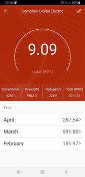
Today was another good solar day so I ran the two underfloor heaters again for the same time as yesterday. At one stage I checked my wifi power meter and the Warpverter was outputting 9,663 watts ... so Nobodybusiness may like to see that. It generated about 33kWh yesterday and will be virtually the same today as well.

Screenshot_20240416-121842_Smart Life.jpg
 
Great stuff Roger !

I have been playing around with various experimental Warpverter circuits for many years.
Voltage droop with load was the very last unresolved problem, and the solution to that turned out to be wonderfully simple.
I only thought of it after my own Warpverter was fully complete and had been running successfully for some time.
Klaus's inverter was the guinea pig for testing this idea.

The type of Hall sensor you need (at your power level) should probably be 500 amps or even higher, the required output voltage swing with current is after all not very great, even a 1,000 amp Hall sensor would be fine.

The Hall sensor to get should be the +5v powered, amplified type, and it should have the zero current output point set at mid power rail voltage, so it can measure +/- current flowing in either direction with a total output voltage swing from +0.5v up to +4.5v.

That is pretty ideal, because the compensation pot can be tweaked without it also interacting with the inverter ac output voltage at zero load.

Its just then a case of loading up the inverter, and tweaking the pot to bring the inverter output back to the required voltage with some fairly serious load applied. That could be done to keep the voltage at the house constant. The ac voltage right at the inverter will then be found to increase slightly with increasing load, because of voltage drop in the long cable back to the house.

This circuit is very fast acting, and should go a long way to reducing light flicker with short power surges and large step load changes, as well as correcting the steady state voltage.
 
Hall effect?
Why not CT on AC side, process the output however you like (e.g. rectify and filter.)
 
Hall effect?
Why not CT on AC side, process the output however you like (e.g. rectify and filter.)
Output of Hall effect is direct dc, and its also sensitive to current direction (normal inverter load, versus battery back charging).
The whole feed forward concept works extremely well for an inverter, yet I have yet to see anyone else design an inverter that way.
Its much faster, with far better dynamics than any feedback control loop, and without any risk of instability.

The biggest issue with feedback is the "rectify and filter" problem of measuring the ac output voltage.
Trying to measure sudden ac voltage step changes accurately and quickly is not that easy without introducing time delay and settling time issues.
Tuning PID feedback loops also introduces further phase and time delays on top of that. If you try to make it correct faster, it becomes unstable.

Dc voltages and currents at the inverter input are dead easy to measure very fast with a simple snap shot analog to digital conversion, and the results applied to the appropriate gain adjustment of the inverter output just as instantly.
Full output voltage correction in half a cycle or less are theoretically possible. The Warpverter takes two ac output cycles to correct which seems to work well enough.

The slow ramping correction required of a feedback loop, does give much better long term steady state voltage regulation, than feed forward.
But for very large step load changes, and very short inrush surges, the much better dynamics of feed forward win hands down.

No reason why feed forward cannot be applied to a PWM inverter, its just never been done as far as I know.
That would be very easy to implement with a microcontroller, and it could even have a very slow feedback component added to it as well.

Automotive engine management systems all work this way. All the inputs, rpm, load, engine and air temperature go into a system of lookup tables, and spark timing and fuel are set according to all the stored lookup table values. Its the only way to get the whole mess to respond fast enough during spirited driving.

A very slow learning algorithm controlled by an exhaust gas lambda sensor, often works in conjunction with all that to cater for long term engine wear and long term sensor drift.

Its all so much easier with an inverter. There are only two inputs, dc voltage and dc current going into the inverter, and the output voltage can be precisely anticipated from only those two inputs. And they are both perfectly linear, and dc is particularly easy to measure quickly and accurately.
I am stuffed if I know why nobody else is doing this.
There is certainly no shortage of software expertise around these days to pull this off.
Its not complicated, I did it with a very simple hardware circuit.
 
Last edited:
I only meant open-loop droop correction. You measure battery current and adjust what tables drive 3x or 4x MSW inverters to create staircase sine wave.

I think DC current and AC current are directly related and have essentially zero delay. There is some difference between transformer primary and transformer secondary, but I think CT(s) could be applied at either place.

Where it gets more complicated is bidirectional current flow, if AC coupling (voltage sag or voltage rise.)
 
Dc can be measured very quickly at any time.
Ac requires rectification and averaging, either in hardware or software, and averaging always takes time.

While its true you can peak sample an ac voltage, that is very prone to noise and spikes during the sampling window.
Most accurate and fastest measurement is with a dual slope integrating analog to digital converter measuring dc.
The integration function averages out any impulse noise, while still being reasonably fast.
 
Back
Top