diy solar

diy solar

Warpverter

Transformers like 240/480 to 120/240 give several voltage options, even just driving the primary, not backfeeding secondary.
480:120 = 4:1, 480:240 = 2:1, 240:240 = 1:1
There is also 600 to 120/240, 600:120 = 5:1
And 120/240 to 12/24, 10:1 or 20:1
Pick the VA rating of each appropriately.

Just using the first three ratios, 100V in gives 100V + 50V + 25V = 175V peak, about right for 120Vrms.
With 2 transformers for 2x 480:120, 1 transformer for 2x 240:120, 1 transformer for 2x 120:120, four physical transformers should take in 100V of battery, produce 120/240V split-phase.
 
Its fed from a huge fork lift battery, the transformers are so large that they will easily absorb massive short bursts of heat, so I imagine the mosfets would set the absolute limit. The largest inverter has four groups of six HY4008's, but the other inverters contribute something to that as well.

Difficult to say really.
Looking at the HY4008 data sheet it says 153 amps per device continuous at 100 C junction temperature.
https://datasheet4u.com/datasheet-pdf/HOOYI/HY4008/pdf.php?id=1300514
Each device in the bridge is on for less than 50% of the time in the largest inverter.
A rough conservative guess might be switching 6 x 150 amps should be well within their capability with a reasonable heat sink.
900 amps at 45v dc is just over 40Kw. It could be more than that.....

Roger is running a 63 amp thermal/magnetic circuit breaker (15 Kw) so that should open well before anything goes bang.
That’s impressive..
 
I think you can repurpose an assortment of utility transformers. A number of different ratios are available. It looked to me like I could do it without any custom winding.
I don’t remember fully now but it wasn’t just about ratio but impedance matching and other things.

I’m sure you probably could but I think I would have to wind my own.
At least at first.
I have been on that site lurking since warp speed told me about these little devices.

I am slowly coming to terms with what is needed.
 
Impedance of transformer windings (at lower frequency) is primarily a ratio of impedance connected to its other windings.
High frequency, capacitance and self resonance comes into play. But at operating frequency, I think transformer's impedance is negligible. Except for a bit of filtering of harmonics. (story is that the designers at Trace wound to achieve desired amount of leakage inductance, which took care of filtering without outside components.)

The thing about warpverter, as I understand, is that it doesn't care about impedance or anything. It is a bunch of MSW inverters connected in series. Each just forces some ratio of battery voltage to its output. Within some frequency range where transformer is able to do its job, it is similar to switching series connections of battery onto a load, to produce stair-step approximation of sine wave. Power flows into or out of battery freely, acting as a 4-quadrant amplifier for the controlling sine-wave digital signal.
 
There are quite a few layers of complexity in all this that can be difficult to think through.
The whole concept is pretty unusual and largely unexplored territory.

If you just run the largest transformer all by itself there will be massive overshoot (expect 30% to 40%) and some slight ringing.
Transformers definitely do not like producing a square wave current !

Add inverter two, and the waveforms looks pretty awful, the steps and edges slope and it all looks rather ragged.
I have warned Warpverter builders to expect this, and not to become disillusioned, there is nothing really wrong.
As the third, and particularly the fourth inverter are added, ALL the waveforms clean right up, the improvement is both massive and magical !

All four transformers become really happy conducting a pure low distortion sine wave current, and all the rectangular voltage edges clean right up as well. Its a fascinating thing to see.
All the harmonics cancel right out. I am sure it does wonders to reduce eddy current loss too, but have not really investigated that.
The low idling powers that can be achieved, suggest low core loss, much lower than I thought possible for such large transformers.
 
Hi Tony,

Just read through this thread, and what a interesting read.

I have attached a PDF file from the 'OzInverter' book Tech chapter, that you wrote up a few pages for me, about your clever design and build of the 'Warpverter'. I trust this is okay?

Roger's 'Warpverter' looks real nice my hat is duly raised.

I have been pointing folk towards the 'Warpverter', when they ask me about the best Inverter ever, and i trust 'Roger' will carry the 'Warpverter' forward.
 

Attachments

  • WarpstepInverter.pdf
    1,015.7 KB · Views: 30
Hi Tony,

I have attached a PDF file from the 'OzInverter' book Tech chapter, that you wrote up a few pages for me.
Hi Leslie, really good to hear from you again.
Golly, its been quite a few years since I wrote that, it certainly brings back memories.

For anyone contemplating going off grid and home building an inverter, Leslie's book is an excellent source of knowledge and ideas.
Its basically a distillation of many of the projects and threads over at The Back Shed forum over the years, and a great place to start researching the building of an inverter, specifically the PWM Ozinverter which is recommended up to around 5Kw.
It also includes the above introductory information about the Warpverter, which would be a better approach at higher power levels..
https://levivray.com/new-book--make-a-6kw-inverter.php
 
Hi Tony,

I have given up on supplying the 3 PCB's as Country's Customs have become a real stop on small PCB batches, especially those A4 double thick copper Power boards of mine. I have a few control boards, 50HZ and 60HZ, and cooling boards in stock, so i will offer them for the meantime.

Once somebody has ordered the book, and has my email address i can, if they wish, email them with my XGerber files for the PCB manufacturing process in thier own Country.

I have moved all my tech stuff over to my old Microengineering site, yea it rambles around a bit but all books, ........... OzInverter, 3.7m dia Wind Turbines 3.2kW PV solar trackers and other projects will be there. Still non comercial, and as long as i get my money/expences back my projects are still fun to help others who want to learn.

I have another 4 books in the process of compiling, but the real fun one is the 'Make your own 450ah 2v Modern version of the PLANTE lead acid battery'. Been working on and off on this project for over a year now and i do occasionally post/update on the 'Backshed' and 'Fieldlines' .

Take care Tony,
Best wishes Leslie.
 
While we're on the topic of the OzInverter - did anyone of you know that (at least the power board) is used in several commercially available inverters (including from MUST, POWER STAR, FELICITY - all very popular on the African continent).

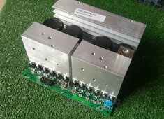
Here is the one that's in a MUST EP3000 Plus (taken from some website, but I have one of these inverters and it's definitely this one):

43667281_20200412-155907_1_1500x1125.jpg
 
While we're on the topic of the OzInverter - did anyone of you know that (at least the power board) is used in several commercially available inverters (including from MUST, POWER STAR, FELICITY - all very popular on the African continent).

Here is the one that's in a MUST EP3000 Plus (taken from some website, but I have one of these inverters and it's definitely this one):

View attachment 192920

Looks like the old (about 2013) Power Jack power board. They were good up to about 3kw and a smallish toroid.

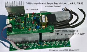
Here is a photo of my design, based from the W7 PowerStar that 'Oztules' worked with. The Chinese used the W7 for the Later PowerJacks.
 

Attachments

  • OzBoardsAssTIPHeatS2019.jpg
    OzBoardsAssTIPHeatS2019.jpg
    391.3 KB · Views: 11
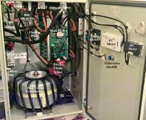
Here is a picture of the inside, including the toroid (total weight about 35kg):

dsc_2333-preview3-jpg.32591
 
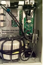
Here is big Ozinverter, toroid assembly is 42kg. And the standard OzInverter with a toroid of 30kg.
 

Attachments

  • Oz2Assembly8kWJan2019.jpg
    Oz2Assembly8kWJan2019.jpg
    143.1 KB · Views: 10
  • CaseInside2.jpg
    CaseInside2.jpg
    276.7 KB · Views: 10
Last edited:
I thought that some of you might want a good tech read about Inverters.

It shows the development and general tech explanations of the PWM inverters and other concepts.

I therefore hereby release my Chapter 14, Tech Info, as a PDF. Leslie Bryan, 03 Feb 2024..
 

Attachments

  • Chpt142019Feb2024c.pdf
    2.1 MB · Views: 19
There were a lot of discussions and some arguments about chokes back in the early days over at the Back Shed.
It took quite a long time before a lot of people believed that a choke was even necessary !
The original Oz inverters used no choke and they appeared to work just fine.
A lot has been learned since then, and the learning curve is still ongoing today.

Interestingly, as the guys over at Back Shed were making real progress with much diminished idling current, and far fewer blow ups, we started to see chokes appearing in Chinese products. It appears the Chinese follow our progress here with great interest.
 
There were a lot of discussions and some arguments about chokes back in the early days over at the Back Shed

Read through this whole thread yesterday about Roll your own MPPT over at the Back Shed.
Lot of discussion there also about chokes.
Goes back to early 2020. ~50 pages. Now I've got to read through it again.
@clockmanfr , I also ordered your Ozinverter book on Friday. Thank you for sharing.

Randall
 
Designing chokes is a particularly complex subject to get ones head around.
Unlike most electronic design tasks, there are no step by step design rules to follow, that will lead directly to an optimum design.
Its basically "make a guess" and then see how all the numbers turn out, and if its practical.
Change a few things, and start all over again.
 
Back
Top