diy solar

diy solar

Warpverter

DIY Inverters, Making the Toroid transformer. From the OzInverter book Chapter 4.

The toroid is the most effiecent transformer, with only small losses compared to the standard EI square lanimated transformers.

This Chapter 4 contains all the required info on making your own torroids for an Inverter, it shows actual practise and how to assemble and wind.

Most of the info is for a 6kW (real running inverter 48vdc to 120vac or 230vac). As you can see its all about the actual mass/weight of the bare toroid and you can therfore extrapulate the calculations to suit what you require.
I also show the Secondary and Primary windings and their respective count calculations, again these can be extrapulated to suit what you want.
 

Attachments

  • ToroidChapter5.pdf
    2.4 MB · Views: 12
Measure BH curve of choke. You can make a Chan model in LT Spice. I found that did quite well in showing how they behaved in circuit, at least relative performance of different chokes.

The hysteresis curves of different materials vary widely, are optimized for different purposes. Manufacturers publish only part of the data, so you have to measure and model on your own.
Magnetization curve is certainly important for the dc ampere turns through the choke aspect.

Along with that, we need to think about the superimposed ac ripple, and the effects that will have on core loss and skin effect.
Then there is temperature rise of both core and wire.

And we might need to think about possible resonance effect, both internal, and external, when connected into the actual circuit.
Size and cost considerations too perhaps.

There is so much to think about, and so many factors are interrelated, and it becomes a judgement call on how best to balance things.
Fixing a problem in one area can very easily make problems in another area worse.
Choke design is an excellent way to drive yourself nuts....
 
Sure, but saturation and hysteresis are a key part of choke behavior.
I think you can get lower hysteresis in a choke than a transformer, so optimize selection of materials.

I tried to use a toroid transformer as low-frequency choke, reasoning it was optimzied for low frequency behavior. Such a transformer only a few times larger than a choke with nanocrystaline core performed significantly worse. It took a toroid transformer many times larger than the choke to beat its performance, in my application.

I think the Warpverter design will already have relatively little high-frequency content, unlike PWM synthesis of sine wave. So less demand on the choke, and skin effect likely not so much of a problem. I haven't looked into that, although I did use 30 awg silver-plated wire wrap wire for an 11 MHz transformer. There, self-resonance was a problem with "enamel" magnet wire. The 10 mil Kynar insulation of wire-wrap wire fixed that.

I highly recommend measurement and modeling of BH curve. There is an EEVblog on it, with link to a video from MIT.

Rather than analog integrator, I did that with scope digital functions or Matlab. I used a variac and series resistor to apply signal (step down through another transformer for chokes that can only hold off about 1V at 60 Hz, as opposed to transformers good for 120V or 240V.)

Also in LTSpice, try to use math rather than analog components. Easier to tweek for different values and frequencies.
 
Sure, but saturation and hysteresis are a key part of choke behavior.
Its only one part, and it may be a quite small part.
By definition a choke has "some" dc component (an inductor does not).

Now the ratio of dc to ac is extremely important in choke design.
Two extremes might be a noise reduction choke in the output of a very high dc current switching power supply.
Maybe 50 amps dc, and 50mV of ac noise.

The other extreme might be a 3Kv boost converter choke. Huge ac voltage, but only a few milliamps of dc.
Both might require very similar inductance !
But other than the inductance, they will have absolutely nothing else in common.
 
This looks similar in approach to the old Trace SW series - although I think they used a single transformer core with multiple windings. Have you ever looked at that design?
 
This looks similar in approach to the old Trace SW series - although I think they used a single transformer core with multiple windings. Have you ever looked at that design?
Yes its a very similar approach in principle, but there are also some quite major differences.

Trace uses three individual transformers, as you can clearly see by the simplified circuit, and pictures in post #31 on page 3.
 
Sure, but saturation and hysteresis are a key part of choke behavior.
I think you can get lower hysteresis in a choke than a transformer, so optimize selection of materials.

I tried to use a toroid transformer as low-frequency choke, reasoning it was optimzied for low frequency behavior. Such a transformer only a few times larger than a choke with nanocrystaline core performed significantly worse. It took a toroid transformer many times larger than the choke to beat its performance, in my application.

I think the Warpverter design will already have relatively little high-frequency content, unlike PWM synthesis of sine wave. So less demand on the choke, and skin effect likely not so much of a problem. I haven't looked into that, although I did use 30 awg silver-plated wire wrap wire for an 11 MHz transformer. There, self-resonance was a problem with "enamel" magnet wire. The 10 mil Kynar insulation of wire-wrap wire fixed that.

I highly recommend measurement and modeling of BH curve. There is an EEVblog on it, with link to a video from MIT.

Rather than analog integrator, I did that with scope digital functions or Matlab. I used a variac and series resistor to apply signal (step down through another transformer for chokes that can only hold off about 1V at 60 Hz, as opposed to transformers good for 120V or 240V.)

Also in LTSpice, try to use math rather than analog components. Easier to tweek for different values and frequencies.
Not really any suprise that toroid transformer core doesn't work as a choke. It has high relative permeability (>2000) and it means that it will saturate at very low current. Probably takes only tens of milliamps DC to saturate toroid transformer primary.
You would need to gap it to lower the permeability but gapping wound toroid cores is easier said than done.

For chokes or inductors you generally want the relative permeability somewhere between 20 to 100. I'd start at 40. For ferrite or iron lamination E-cores the required air gap is easy to calculate.
With distributed air gap material(MPP, Sendust, iron powder) you are stuck at what is available from market ie.
Yes, toroids wound from silicon steel are only suitable for transformers or inductors where there is zero dc current.

But you can buy U cores made from exactly the same wound silicon steel as the toroids. Instead of being wound over a round mandrel, they are wound over a rectangular mandrel, then cut in half. That allows the incorporation of an air gap, and these do make wonderfully cost effective high power chokes for some applications.

A choke by definition has to carry a dc current, but also support an ac voltage across the choke. When designing a choke both these requirements must be met, and both requirements can cover a huge range for different applications. That is why there is such a very wide choice of core materials available. And then you get to choose either an ungapped core of suitable permeability, or a gapped core where you can adjust the permeability to get exactly what is needed by experimentation with the gap. This offers obvious advantages for an experimental project.

There are some fundamental requirements that ALL need to be met when deciding if a particular choke is going to be effective.
The basic ones are:

How much inductance will it have with both high and low dc current..
Will it saturate, and will it have soft, or a brick wall saturation characteristic.
Will the core material overheat.
Will the wire overheat.

But there are some other requirements too:

Will the choke be operating well below self resonance.
Will the choke in combination with external capacitance produce a resonance (it always will) but is it going to be harmful.
Will ripple current be high enough that skin effect in the wire becomes a problem.
Is the insulation up to the job.

These factors individually can end up being of negligible significance, to presenting a horrific and insurmountable problem depending on what the choke is being used for. The art of choke design is in deciding what is important for a particular application, and trying a few different approaches using published data. There is no direct method of reaching an optimum solution very first try. Its an iterative process, first on paper, then maybe with some real world testing and experimentation. Ten different choke designers will come up with ten very different designs.
Some will work better than others, some may be smaller or cheaper. But they will probably in the end all be usable.
 
I was operating the toroid as common-mode choke. Several amps L1 and L2 in opposite directions so not saturated. That let the core address just common mode and imbalance due to any capacitive loads. I used 9V secondary windings rather than primary windings.

I used the same 100VA transformers to build an amplifier, for fun. Use DC bias current to vary how far into saturation.

A different BH curve might work better. This just allowed current to bleed through in one polarity. I think E-core with 2 DC windings would be better than two toroid transformers (back EMF of one transformer cancels the other, so battery doesn't see very high AC voltage.)

I couldn't get a model that reflected choke performance at first, so went by bench tests. Later I learned to extract Chan model parameters and was able to predict my measurements after the fact.
 
Been thinking about the 'Warpverter' for use in ac coupleing and back charging to the batteries. ????
 
Okay good to know.

With the OzInverter we keep the windings reasonably tight on the winding counts, so we have reasonable headroom at about 44vdc to 62vdc of back charging the battery.

I have used 3 main methods to control the raw back charging by controling the AC back charging GTI's. So for the 'Warpverter', nothing should be much different ?

Below is my published simple explanation on controlling that raw DC backcharging.

A very cost-effective solution for handling over 15kw of power from the PV panels arrays, etc, is to use what is called 'AC Coupling'.

Houses that you see around the World with PV on the roofs will be using standard manufactured GTI's, (Grid Tied Inverters) that take the PV DC output and change it to AC and feed it back at a few volts more into the Mains Utilities Grid for that Country.

These GTI's are slave machines and need to see the correct AC voltage and the correct HZ frequency, so to get their internal electronics/transformer to operate before they will feed into the Grid a few volts over the Mains Utilities supplied voltage.

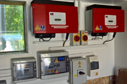
There are many Good Quality GTI's available second hand, i use fleebay etc, and i prefer GTI's with a toroid transformer, see below photo of previously used SMA's........ . 150 to 300 Euros/$ each.

Our 48vdc ‘OzInverter’ H Bridge, creates a very stable 240vac or 120vac at a stable 50H or 60HZ, depends on your country domestic voltage, and therefore allows 'AC Coupling'. The GTI's back charge through the ‘OzInverter’ to the battery bank any surplus power not being used on the OFF GRID or we call our ‘OzInverter’ created MINI GRID.

Three methods of controlling the back charging from GTI's is possible for 'AC Coupling'.

A. Use the Internal codes/settings in the GTI's to sequential shut down when a specified ac output voltage is reached. This works reasonably well with my system as some installations GTI,s are up to 400 meters away from the ‘OzInverter’ and batteries, and the batteries do push back slightly, but this depends on the cable voltage sag.

B. Use dc voltage comparators circuit to shut down the GTI Ac side with a relay when the DC battery voltage rises above a charging rate voltage. But you will need to run a data cable to all your installations, and again allow for voltage sag.

C. Use PWM dc controllers that are connected directly to the 48vdc battery bank. These Diversion controllers, (Morningstar Tristar PWM at about 200 Euros each), will regulate the charging and any excess power when the batteries are full and will dump/divert to other permanently connected sources, ie, Air Heaters 2kW each or Hot water heaters, underfloor electric heating, etc.

The above are a cost effective and very reliable system.

A is used most, and C is my guaranteed safety system. Where i do not have access to the GTI internals, then i use B.

For a 19kW Array I prefer using 2off 1.7kW & 4off 2.5kW GTI's for 15kW, and using DC Charge controllers for the 5kW as these can gently finish charging that precious 48vdc battery bank.

NOTE, I have not used a HF, High Frequency GTI, because second hand old heavy toroidal types are easily obtainable and very cheap, plus you get to use the GTI internal MPPT . 'Oztules' and others have experimented with HF types and do not find any real difficulties.

NOTE. Its best to use GTI’s at a max output of 2.5kW as above this, the GTI tends to surge on a long cable connection and constantly triggering on and off on the bigger GTI's.

NOTE, So importantly the GTI’s output will always be used by your appliances etc, on the Mini grid you are creating, and your battery bank will not really be used until the sun goes down, then the battery bank will step in to use the main Inverter and run the appliances etc.

The two red boxes in the below photo are standard old GTI's that are used/second hand.
Each is rated at 1.8kW and capable of converting the ever-fluctuating sun shining PV DC voltage to 240vAC to feed into our MINI GRID. This Garage roof PV install has 3.6kW max of PV and i have spilt them into 2 PV strings of 1.8kW each so just about correct for each GTI.

.
1708858480763.png
 
All of the above should also work just as well with a Warpverter.
Oz inverter or Warpverter are functionally just devices to turn dc into ac with some voltage regulation of the ac, and very little other functionality beyond that.

The biggest differences will probably be at the grid tie end, and what features and functionality exists there.
All grid tie inverters work under software control, and how that works with regard to triggering shutdown, and possibly some serial data communications availability, will depend on specific make/model of GTI.

I have never tried back charging personally, I don't have an installed GTI, and my own system is quite small and very simple.
Other Warpverter users have successfully back charged through a Warpverter without any problems.
 
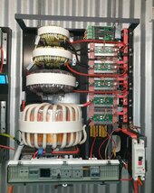
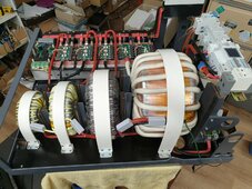
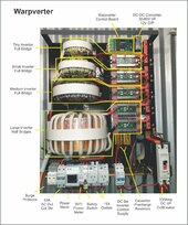
I've been following this thread with interest and wondered if anyone might want to see my efforts at building a Warpverter. It's been a long slow slog over several years but it is finally up and running ... and will finally be connected to run our place within a week.

And I have to thank Warpspeed for his generosity in not only freely sharing his concept and design ... but providing an enormous amount of tech and moral support along the way. And thanks Tony also for the contol board, ROM and oscillator module and all your time answering emails back and forth.

I'm pretty sure he thought at times he wasn't going to live long enough to see it finished ... but it's finally here. 😁 Though having said that, I still need to build the front cover and fit appropriate metering and controls etc.


Warpverter1.jpg

Warpverter4.jpg

WarpverterBreakdown.jpg
 
Are those few turns of plastic insulated wire really enough to hold off (what?) battery voltage?
Must be a hell of a lot of coupling to the core.

"Finally up and running" - what abuse have you given it so far in testing?
 
Are those few turns of plastic insulated wire really enough to hold off (what?) battery voltage?
Must be a hell of a lot of coupling to the core.
Roger has a really huge 48v fork lift battery.
Its a pretty big core, and there are sufficient turns for only 1 Tesla.
This is the KING of Warpverters, the largest built so far. 15Kw continuous, and plenty of surge capacity well beyond that.
The workmanship is absolutely superb, its a real show piece and something to be really proud of.

Well done Roger !!
 
"Finally up and running" - what abuse have you given it so far in testing?
That was really more in reference to me finally getting my butt into gear and off of facebook and various platforms, and doing the tasks needed to complete what I started. :)

Having said that, when I first fired it up and started checking it out, I blew 6 mosfets on the medium tx bridge. I replaced them and it ran again with say a 15 watt load ... then soon after all 12 of the mosfets on a large tx half-bridge blew.

After the initial panic and stopping to think about it, I realised I hadn't considered the dead-time ... I had just used the value from the original circuit which was about 200nSec. To be on the safe side I widened it out to 2.3uS by changing the "dead-time" caps from 1nF to 10nF and tried again. That seems to have solved the problem, though Tony suggested that I could really widen it out to tens of microseconds if I needed to due to the low speed switching involved.

As far as "abuse" ... I'm not sure I've really abused it yet. It's up to 345kWh of production and most of that has been 8-12hr runs of 1 or 2 pool pumps along with intermittantly boiling a kettle, running a heater and the occasional switching on of the air compressor. I'm not really all that brave, so need to get a bit more gung-ho. :) The highest load I've put on it for any time was a bit over 5kW.

The idle power is 35 watts, though 9 watts of that is to run the DC-DC converter to drop from battery volts to 12v which in turn run an additional 12 isolated dc-dc converters (12v-15v) on the bridge boards.

Oh and thanks for the kind words Tony and again for all your help.
 
Back
Top