


You are using an out of date browser. It may not display this or other websites correctly.
You should upgrade or use an alternative browser.
You should upgrade or use an alternative browser.
Renogy DC DC Charger w/ MPPT
- Thread starter Will Prowse
- Start date
I've had a good crack at implementing Will's blueprint with the addition of a Renogy battery monitor and a Bayite as a total DC load monitor. I hooked it all up to car as follows, 4 gauge wire everywhere (minus the solar and solar shunt/ monitor as don't have the panel yet) and spent time with some free software getting this swanky wiring diagram together, but I suffering a reverse polarity situation according to the battery monitor.

I've got the battery monitor showing all the current coming down the line when the alternator is running which is great i.e showing +37A etc.. and the load monitor showing the fridge draw 5A. However, with the running alternator/ starter battery pushing charge down the line through to the auxiliary battery (105Ah Lithium) the battery monitor complains and flashes "reverse polarity" - if I disconnect the running alternator/ starter battery leaving only the running fridge in the circuit, the battery monitor behaves and happily shows the current draw created by the fridge with no complaints about incorrect polarity.
I tried switching the cabling around on the battery monitor shunt, which, resulted in the battery monitor showing -37A with correct polarity when the alternator is running and pushing charge through to the auxiliary battery.
Any ideas/ suggestions would be bloody fantastic as I'm doing my marbles!")
I've got the battery monitor showing all the current coming down the line when the alternator is running which is great i.e showing +37A etc.. and the load monitor showing the fridge draw 5A. However, with the running alternator/ starter battery pushing charge down the line through to the auxiliary battery (105Ah Lithium) the battery monitor complains and flashes "reverse polarity" - if I disconnect the running alternator/ starter battery leaving only the running fridge in the circuit, the battery monitor behaves and happily shows the current draw created by the fridge with no complaints about incorrect polarity.
I tried switching the cabling around on the battery monitor shunt, which, resulted in the battery monitor showing -37A with correct polarity when the alternator is running and pushing charge through to the auxiliary battery.
Any ideas/ suggestions would be bloody fantastic as I'm doing my marbles!
RandyP
Solar Enthusiast
- Joined
- Sep 21, 2019
- Messages
- 742
I've had a good crack at implementing Will's blueprint with the addition of a Renogy battery monitor and a Bayite as a total DC load monitor. I hooked it all up to car as follows, 4 gauge wire everywhere (minus the solar and solar shunt/ monitor as don't have the panel yet) and spent time with some free software getting this swanky wiring diagram together, but I suffering a reverse polarity situation according to the battery monitor.
.............
The wiring is a little 'different', but that's OK.
The switch in the - wire from the start battery, I don't see that often. I'd suggest you put that in the + wire from the start battery.
I see that the starting battery - is chassis grounded. The LiFePO4 - should also be chassis grounded.
Wire from - LiFePO4 should go to the - bus bar.
Wire from solar panel - should go to - bus bar.
I would add a small circuit breaker switch to the + circuit from the solar panel to the DCC50S + solar input. That way you can isolate the DCC50S from the solar panel.
I would use a small circuit breaker/switch in place of the fuse in the wire from the LiFePO4 + circuit to the DCC50S +. That way the DCC50S can be easily isolated from the LiFePO4.
I do not know why you are getting incorrect polarity indications.
boondox
Chief Engineer, RedNeckTech Industries
- Joined
- Mar 1, 2020
- Messages
- 789
Jbamps, you might want to start another thread with your questions. This is not a BMS thread.
So, looking at making a custom user profile for my Fortune 100aH cells. How does this look?
HV disconnect : 16
Charge limit voltage: 15.5
EQ- 15.5 (but we do not want an EQ on LFP)
Boost : 14.6 (manufacturer states 3.65 per cell, is this a little hot?)
Float: 13.8
Boost Char Return: 13.2 (I assume this is when it goes back to boost from float)
Low voltage alarm : 12.1
Over discharge volts: 10.6
Thanks!
RandyP
Solar Enthusiast
- Joined
- Sep 21, 2019
- Messages
- 742
Are these settings the recommendation of Fortune 100aH cells combined for 12v battery ?Jbamps, you might want to start another thread with your questions. This is not a BMS thread.
So, looking at making a custom user profile for my Fortune 100aH cells. How does this look?
HV disconnect : 16
Charge limit voltage: 15.5
EQ- 15.5 (but we do not want an EQ on LFP)
Boost : 14.6 (manufacturer states 3.65 per cell, is this a little hot?)
Float: 13.8
Boost Char Return: 13.2 (I assume this is when it goes back to boost from float)
Low voltage alarm : 12.1
Over discharge volts: 10.6
Thanks!
boondox
Chief Engineer, RedNeckTech Industries
- Joined
- Mar 1, 2020
- Messages
- 789
The data I have for the Fortune cells only lists the max charge voltage (3.65) and the end of discharge voltage (2,2). So what I have listed above is actually the default for an LFP battery with the float voltage changed to 13.8.
boondox
Chief Engineer, RedNeckTech Industries
- Joined
- Mar 1, 2020
- Messages
- 789
Well, bugger. I can't get the BT-2 to connect now! I have turned everything off, restarted my phone, turned BT on and off, unplugged the BT-2. No matter what I do I can't get it to connect, the blue light just endlessly blinks. Really annoying. Any ideas?
@RandyP if the starter is chassis grounded and the starter negative is connected to the DCC50S neg and the LiFePO4 neg is connected to the DCC50S neg that mean that the LiFePO4 is connected to a chassis ground - right?The wiring is a little 'different', but that's OK.
The switch in the - wire from the start battery, I don't see that often. I'd suggest you put that in the + wire from the start battery.
I see that the starting battery - is chassis grounded. The LiFePO4 - should also be chassis grounded.
Wire from - LiFePO4 should go to the - bus bar.
Wire from solar panel - should go to - bus bar.
I would add a small circuit breaker switch to the + circuit from the solar panel to the DCC50S + solar input. That way you can isolate the DCC50S from the solar panel.
I would use a small circuit breaker/switch in place of the fuse in the wire from the LiFePO4 + circuit to the DCC50S +. That way the DCC50S can be easily isolated from the LiFePO4.
I do not know why you are getting incorrect polarity indications.
John Frum
Tell me your problems
- Joined
- Nov 30, 2019
- Messages
- 15,233
in reference to the renogy DCC50S does anyone know if the BVS cable should go to the service battery or the starter battery?
house battery which I guess is the same as service battery
Its not necessary and their manual does not mention it in the install instructions.
RandyP
Solar Enthusiast
- Joined
- Sep 21, 2019
- Messages
- 742
Sure, but the ground should be short, same gauge wire as the Battery + wire. One ground for each battery. It's a current return path for 12v ground faults to clear the batt main fuse. You do not want to run that current thru multiple termination points and devices. It's a code/standard and safety thing. In your mind it might be the same as what you have now, but in realty it is not. Logic is not the only thing you apply for electrical safety. If you comply with codes and standards fr safety, you will be safe.@RandyP if the starter is chassis grounded and the starter negative is connected to the DCC50S neg and the LiFePO4 neg is connected to the DCC50S neg that mean that the LiFePO4 is connected to a chassis ground - right?
RandyP
Solar Enthusiast
- Joined
- Sep 21, 2019
- Messages
- 742
Manual says start battery. It is used to get start battery voltage for control. The current carrying wires from the start battery have a voltage drop across them, so a dedicated circuit for battery voltage is required.in reference to the Renogy DCC50S does anyone know if the BVS cable should go to the service battery or the starter battery?
John Frum
Tell me your problems
- Joined
- Nov 30, 2019
- Messages
- 15,233
Manual says start battery. It is used to get start battery voltage for control. The current carrying wires from the start battery have a voltage drop across them, so a dedicated circuit for battery voltage is required.
I just checked the manual and I don't think it says "starter" battery.
It does show a picture of a battery with an RV on it though.
I guess the dc2dc charger cares what the voltage is at the starter battery because it actually charges the starter battery once the house battery is topped off.
My mistake, not good with pictures.
Check Votronic VCBS https://www.votronic.de/index.php/en/products/battery-charger-series-vbcs-vac-tripleCharging from Alternator and solar panels, plus, is there any option for adding AC charging capability?
It will be the ultimate solution for my RV.
Regards,
HK.
Greatly appreciate the responses here guys. I also reached out to Renogy support and they have since replied as follows:I just checked the manual and I don't think it says "starter" battery.
It does show a picture of a battery with an RV on it though.
I guess the dc2dc charger cares what the voltage is at the starter battery because it actually charges the starter battery once the house battery is topped off.
My mistake, not good with pictures.
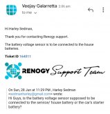
"Hi Harley,
Thank you for contacting Renogy support.
The battery voltage sensor is to be connected to the house batteries."
Ticket ID 164011
---
Attachments
Ok great, that makes sense @RandyP many thanks.Sure, but the ground should be short, same gauge wire as the Battery + wire. One ground for each battery. It's a current return path for 12v ground faults to clear the batt main fuse. You do not want to run that current thru multiple termination points and devices. It's a code/standard and safety thing. In your mind it might be the same as what you have now, but in realty it is not. Logic is not the only thing you apply for electrical safety. If you comply with codes and standards fr safety, you will be safe.
John Frum
Tell me your problems
- Joined
- Nov 30, 2019
- Messages
- 15,233
Greatly appreciate the responses here guys. I also reached out to Renogy support and they have since replied as follows:
"Hi Harley,
Thank you for contacting Renogy support.
The battery voltage sensor is to be connected to the house batteries."
Ticket ID 164011
---
Wow.
Renogy agrees with me but @RandyP convinced me that I was wrong.
In a typical setup I don't see the reason for sense leads to the house battery because it will be pretty close to the dc2dc charger.
The starter battery however could be a significant distance away.
Can someone more neuro-typical than I am have a look at the pictogram in the manual?
I had the BVS connect to the starter battery yesterday and the voltmeter showing house battery (105Ah 12V LiFePO4) voltage went crazy and showed voltage climbing, it got up to 17V then I shut everything down. I'll try BVS connected to house battery later this morning.Wow.
Renogy agrees with me but @RandyP convinced me that I was wrong.
In a typical setup I don't see the reason for sense leads to the house battery because it will be pretty close to the dc2dc charger.
The starter battery however could be a significant distance away.
Can someone more neuro-typical than I am have a look at the pictogram in the manual?
John Frum
Tell me your problems
- Joined
- Nov 30, 2019
- Messages
- 15,233
Similar threads
- Replies
- 16
- Views
- 769
- Replies
- 6
- Views
- 430
- Replies
- 1
- Views
- 632
- Replies
- 0
- Views
- 160