diy solar

diy solar

Using solar micro inverters with batteries instead of panels

@zanydroid I agree that micro inverter producers rely on the fact that the solar panel wont produce more current than the max current rating of the inverter. I noticed that ncsolarelectric’s is a mosfet current regulator that is done very nicely, in theory I should be able to do a more rudimental version of it. (I used something similar for gain clone amplifier, nearly 20 years ago.. time goes too fast ? )
Maybe if I add a LCL filter on the output of the DC-DC converter to reduce the spikes.

@mestariviheltaja so you think just a soft start would be enough ?

ps: silly chinese man and me, I burnt a cheap DC Amp meter, the cables colors in the instructions don't correspond to what I got... magic smoke escaped ?
 
Maybe if I add a LCL filter on the output of the DC-DC converter to reduce the spikes.
There was a discussion somewhere earlier in the thread about this.

I think the concern was that the capacitors in the microinverter are probably only specced for the ripple from the microinverter MPPT and not anything introduced by the power source (since a panel is only going to vary based on slow changing environmental conditions)

Another use for input power limiting in this thread was to throttle the microinverter output, but you have the zero export box managing this .
 
I have zero export set, but maybe also reducing the max output wold help, this 600W inverter sometimes outputs 612W. But I dont have acces, so I would have to call my supplier and ask him to reduce the output. As soon I find the time I will make a test with a power tool battery and DC-DC converter. Only problem is, that Idon't have the installer software, as only use I have access to user the app or cloud that refreshes the data every 15min, so to see the microinverter parameters I have to run a test at least for 20 to 30min
 
I have zero export set, but maybe also reducing the max output wold help, this 600W inverter sometimes outputs 612W. But I dont have acces, so I would have to call my supplier and ask him to reduce the output. As soon I find the time I will make a test with a power tool battery and DC-DC converter. Only problem is, that Idon't have the installer software, as only use I have access to user the app or cloud that refreshes the data every 15min, so to see the microinverter parameters I have to run a test at least for 20 to 30min
The installer software also has a 15 min reporting lag. I have one array where I have full installer access and another where I only have user access. I haven't tried the RS485 connection

I'm not sure you can combine zero export feature on DTU with overriding the output.

Maybe with OpenDTU & the open source zero export.

Microinverter parameters, might be easier to access with a multimeter / clamp meter. The MPPT voltage will not change (since you're connecting to a stiff source). The DC and AC current would vary though.
 
@mestariviheltaja so you think just a soft start would be enough ?
In my current setup on my Powerwall I have
- 4pcs Envertech 500 microinverters and
- 2pcs GTIL 1000W inverters
all connected to Tesla model S batteries (2s2p = ~48VDC) via a latching relay including a precharge circuit.

The precharging is done by first connecting a 50 ohm resistor in series. After 15 sec the latching relay is connected in parallel with the precharging circuit.

The inverters does not have panels connected at all.
On the AC side on the inverters I have relays. With these relays I can make sure that DC is never connected nor disconnected under load since the main controller disconnects the AC side before controlling the DC relay

This setup has been running for a few years now
 
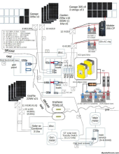
Just found this thread, still reading the whole thing. For 2-3 years now, I've been using old m190/m210 microinverters to discharge 10s and 14s Leaf cell battery banks now totaling about 30kwh, runs everything for a night or maybe two, depending on cloudy days. They are AC coupled into SMA SI6048US main inverters w/ FLA forklift batteries, and normally the whole house is off-grid behind those inverters. Wintertime or string of cloudy days, need some from the grid off-peak, but on-peak 11a-7p always off-grid even if have to take some out of the FLA.
Most of the solar is AC coupled with microinverters, and some goes direct to the 14s lithium battery bank.

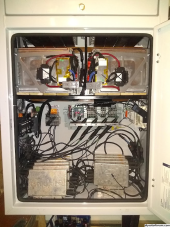
The goals with the battery microinverters are to minimize the cycling of the lead batteries, keeping them mostly full & floating, fine for any big loads the house may throw at it, and use these other voltage and chemistry packs. A RPi talks to the main inverters, battery bmss, etc, and decides how many microinverters to enable, via wifi relay boards that switch one of the 240v legs. The other 240 leg is normally connected, as is the DC input side. The battery banks have multiple paralleled packs each with a BMS. The RPi keeps the discharging within the range of the BMSs which normally don't trip. One pack is charged direct from DC solar charge controller, and the 10s pack in an Electrak tractor has 2x 120v chargers which the RPi turns on when there's enough solar. I have a 120v 40?w chandelier bulb as a precharge circuit for the DC side of microinverters, before closing the DC breaker going to the microinverters, wait until the lightbulb has gone off. Don't wait too long though, as the micros try to start up like it's morning and there's sun out, then the bulb starts glowing again.

I was able to edit the grid profiles of the m190/m210 micros to restart after 10s of seeing 'grid', using the older white oval Envoy.

So, yeah, hook batteries direct to microinverters, it works fine. A battery is like a huge solar panel, at least for lithium batteries, a microinverter goofing around doing MPPT is not changing the voltage, it just runs at max output of the microinverter. Switch the AC side to control them individually, most any tiny relay can handle 240v AC at less than an amp, for these ~200w microinverters.

I have a new question: I just picked up a pair of 9s Leaf modules that I'd like to use, each with it's own BMS. I'm wondering about some sort of controllable (pwm, analog or serial data) DCDC converter that I could piggyback these 9s modules on the main inverter DC bus (as if it was a solar charge controller directly charging the FLA battery, which I used to do). Otherwise, need to set up more microinverters to discharge this pack, and either an AC to DC charger from excess solar. Anyone have ideas about how to make use of yet another voltage battery bank? Thanks!

1702006141604.png1702006201566.png1702006318195.png

Too many more pictures: https://photos.app.goo.gl/q1euFhioH266nPvW9
 
Last edited:
What is this particular PWM module that you speak of?

Oh I see now
 
Last edited:
Interesting overview of nighttime consumption of Enphase Microinverters (applicable to any inverter):
(no pun intended ;)), but at least it confirms that the 8 x 2700uF caps I see in my NEP 590W dual Microinverters are on the DC input.
Hah, Horrors! I thought they use a little power overnight, but I guess it's really mostly the Envoy using power overnight. I turn mine off at night! Since I made a contactor transfer switch for the main grid-tied array, I leave it off at night. Might save lifetime on the AC side capacitors having them turned off at night? Also prevents any lightning strikes from the grid getting into the array and microinverters, and prevents any lighting that hits the array from getting into the house, at least by L1,L2. No stopping N,G, but hopefully that's just going to ground. https://photos.app.goo.gl/UcDfekbC1J3qAJ6J9 If it's only the Envoy load, one could put a smart plug on it to turn off at night.

I have other microinverters on the off-grid side of the system, behind the main battery inverters, and those I leave on. The EEVblog video relieves me from the guilt of their extra load (he says no there's no extra load from the microinverters). In fact, maybe they're making it easier on my main battery inverters, but having the extra capacitance on the AC side. But copper losses though....
 
Last edited:
There are 3 broad architectures / circuits being pursued to power Microinverters from batteries in the recent posts of the thread:

DIRECT FROM BATTERY:

kundip has been running a direct from battery circuit for over 2 years now and the only real question we are trying to get a handle on is what effective round-trip resistance he has in that circuit and why he has had no issue with Resistance Check Fault conditions if others are unable to get a similar circuit working.

AGT also has a direct from battery circuit working but in his case, he is using a 4 Ohm inline resistance to pass the Resistance Check / MPPT Lock-on phase and switching from 4 Ohms to a 0.05 Ohms power resistor after power generation starts (and likely closer to 0.07 ohms all-in).
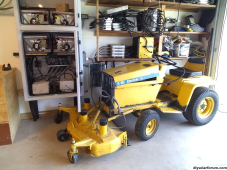
I have had a handful of times where the micros connected to the Electrak tractor have tripped the ground fault detection. Maybe this is what you call resistance check fault. The fault can be reset using the Envoy. The micros set the GFI maybe randomly, I have theories about why, or maybe I'm just doing certain dances to prevent it. The tractor is from the 70s and it from time to time does have a fault from DC+- to AC ground. The tractor's on-board charger has N,L1 going into the tractor, and the AC G is connected to the tractor chassis. So if the tractor and the 70's relay controls have any leakage between battery DC pos or neg to chassis and ground, the microinverters may notice and set the GFI.

If the mower deck is left plugged in, could be a cause, when the deck is turned off, the tractor shorts the motors to stop them rotating. Just a week or two, the off-board charger anderson connector came loose, and that tripped it. There are two chargers, one on each 120v leg, one in the tractor as original, and one on the shelf in the yellow box. From that off-board charger, there's a 30breaker feeding the micros to the left. There's a precharge lightbulb in the off-board charger, after plugging the tractor back in, wait for the bulb to go out before turning on the 30a breaker. Beyond connection & wire resistances, there is not any extra resistance between the batteries and the micro 'PV' input.
1702007037730.png
 
Last edited:
Also, while it didn’t produce AC, the final test case with no resistors did not trigger the "DC Resistance Low" error! More evidence suggesting my first two m250’s were duds somehow.
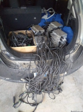
Plenty of old micros are duds. Make friends with a solar installer, they may have piles of them in the woods behind their house, and you just need to plug them in one by one and see if they work. I made several trips like the picture here. My limit was the hand truck capacity per trip.

Be careful testing them. Ground fault light on means the case of the micro could be PV or AC hot. I got a tingle once...

I don't recall finding any bad m190IG, or IQ. Just the older m190/210 style have had poor reliability. Of those, I've found roughly a third that still work correctly, plus others at a reduced power level of say 140w. I've kept those, but haven't tried putting them back in use yet. Every now and then, I check that the battery micros are still producing, I did replace one recently. 1702008206932.png
 
Last edited:
Well, 2 of my IQ7 micros I been powering from my 44V battery bank went dead at the same time (solid red light after bootup) after about 400 kWh of energy exported. Been starting them up via 2 ohm resistor and bypassing after AC power would start to flow.
Sure they're not just GFI tripped? I wouldn't toss them until trying to reset that from your envoy.
 
Mark - Can you detail how you are charging the batteries? Do you have other enphase microinverters for your solar production? Are you able to dyynamically control charge rate? otherwise i'd be worried about limiting PV production when you have an excess of power but the envoy limiting production. Would you be able to have 2 envoys? one for PV production and one for your battery inverters. I'm looking to do the same setup (powering micro inverters via battery during the night to cover the base house load to timeshift without expensive re-wiring. I'm looking to use the common 48v rackmount lithium batteries.
you are likely no longer interested but here is a quick response.

the enphase gateway limits the output of the micro inverted based on the ac requirements from the consumption CT. no timers required for this part and reduces draw on battery when not needed. for charging.. I do have a timer for 9pm off to midnight on. during this 3 hours I have 42v chargers charging my battery packs. these chargers are on a timer. they shut down when 42v is reached. 9 to 12 is free power so I draw significantly on this.

9 micro inverters are connected. most the time only 3 or 4 are all that's needed.


batterys shut down when 32v is reached. ideally I don't want to charge to max or draw to minimum. I did have this controlled via the digital timer to be automatic. when I changed the setup I haven't put this back in and manually monitor.
 
Mine is similar. I have 1 Envoy micro inverter per battery. You can have as many micro inverters as you like.
I have one 24V Battery with 5KW AC capacity running every night for 14 hours @ 300W AC (240 V)
Also one 24V Battery with 1.6KW AC Capacity running every night for 14 hours @ 200W AC (240 V)
Because my system is Micro Inverters everything is 240V AC.
So I charge my batteries during day with good quality 240V chargers.
I don't like the chargers that do everything (AGM, Lead Acid, LiFePo Etc - all in one) (I use Dedicated only)
20Amp is a bit slower but the whole system runs quite cool.
I charge about 8 hours per day.

View attachment 144650
May I ask which app this is? I love data.
 
Note: Over the last three years I have tested so many combinations of devices you would not believe.
Starting with a computer UPS that 4 different electricians said would not work.
What I have distilled is our best observations, that we have shared, over that time.

OK, so the Micro-Inverter directly connected to battery is still running fine, right?
_Yes that is correct

Assuming ~95% efficiency of your Micro-Inverters, 200WAC out requires 210WDC in which is 8.4A @ 25VDC.
_I don't bother working out efficiency.
_With Micro-Inverters I just add more panels if I need more juice.

Would appreciate it if you could provide your Micro-Inverter model or better yet, tell us what it’s maximum input current rating is…
_Enphase M215 is the main model I use.
_Maximum input current is 10.5A https://www.adelaidesolarsafe.com.au/docs/enphase/Enphase_M215_Micro_inverter.pdf

300WAC out requires 315WDC in or 10.5A @ 30VDC out of your voltage booster.
_Yes that is correct.
_Initially I bought the Boost Converters to "control" the current because articles on DIYSolarForum & other places said connecting directly to the battery would fry the Micro-Inverters.
_After buying 3 boost converters I thought I could replicate the above on all three but I could not get any two adjustments the same.
_I tried about 4 different types of cheaper type Boost Converters (up to about AUD $95) but they all had some sort of issue. (Usually adjustment)
_There is certainty in my mind that there may either be a more expensive type of Boost Converter out there that will do the job (I have seen some) or a much better sub $100 Boost Converter will soon be available.
_In the end I tried connecting one Micro-inverter directly and it worked. Talk about the hard way!

And if the booster has efficiency of ~95%, the booster is taking input power of 332W = 13.3A @ 25VDC from the battery.
_Your calculations are correct.
_I don't bother working out efficiency. I did it a few times but I don't see the point.
_With Micro-Inverters I just add more panels if I need more juice.

Sounds like you are either using two different Micro-inverters or perhaps you are pumping the battery voltage up to higher than 32VDC???
_There are 4 different types of micro-inverters on our roof 3 x Enphase 1 x SunnyBoy
_M215's are all I have used for no particular reason. (I got a box of 40 of these M215's for $30 Each brand new)

So you’ve been running both direct-connect and through-booster configurations for over two years now and both have worked fine over that period of continuous use.
_That is correct

Since the booster was not needed, adds complexity, and reduces net efficiency, you’re going to convert that boosted setup to direct-connect as well.
_I did not say "reduces net efficiency" but the Boost Converter runs relatively warm. Add in the reasons outlined above & you can see our train of thought.
_Adjusting the current crop of Boost converters is too hard for a lot of people and more mistakes can be made.
_With our setup of two timers per battery I can run one Micro Inverter for 14 hours. Then if the battery deteriorates I can set the second timer to turn off inside the point where our battery protector kicks in.
_This gives us 3 levels of "protection" ...A. The Timer(s) ...B. The Victron or MotorMate Battery Protector ...C. The BMS on the battery itself

Have I understood all of that correctly?
Hopefully this question is answered.

Our mantra has always been:
To make it simple (using off the shelf parts) so any one can contribute to reducing global warming.
(One battery with a MicroInverter dramatically increases Energy Independence.)
Simple Setup:
Battery Side: Battery & Charger + Fuse
Inverter Side: Battery Protector, Timer, Inverter + Fuse

The reason my wife & I went this way is part of our contribution to reducing CO2 & empower others to do the same.
We could have bought a Tesla Battery but most people cannot afford that & are severely inhibited whilst trying to contribute.
Our system is designed to use the inevitable flood of batteries from electric cars etc.
If you want to start at 48Volt batteries I am thinking it might be best to use the - IQ7Plus.
They can go as high as 60V.

View attachment 143092View attachment 143093

View attachment 144758
B
Thank you for posting all this detail. I want to do this as well. Reading through your posts, I see that this has been a bit of a learning experience. If you had to do things over, what would you do different? I like to do things as simple as possible, but also like automation when it makes sense.
 
Back
Top