diy solar

diy solar

Using solar micro inverters with batteries instead of panels

Well it's worked for two years so far.

Re properly sized to handle load.
Keeping the voltage at the low end seems to work fine. The imicro-nverter can take from 20v to 46v. I stick with 24v. This gives me 200w @ 240vac.

OK, so the Microinverter directly connected to battery is still running fine, right?

Assuming ~95% efficiency of your Microinverters, 200WAC out requires 210WDC in which is 8.4A @ 25VDC.

Would appreciate it if you could provide your Microinverter model or better yet, tell us what it’s maximum input current rating is…
I do have one set up from my original experimentation that has a boost converter taking the voltage from 24vdc to about 32vdc.
This setup produces 300w @ 240vac.
300WAC out requires 315WDC in or 10.5A @ 30VDC out of your voltage booster.

And if the booster has efficiency of ~95%, the booster is taking input power of 332W = 13.3A @ 25VDC from the battery.

Sounds like you are either using two different Microinverters or perhaps you are pumping the battery voltage up to higher than 32VDC???
I plan to change this back to just 24vdc input as the boost converter is not needed and just adds to the complexity.I am not a big fan of the current boost converter design although I have had no problems with it.
So you’ve been running both direct-connect and through-booster configurations for over two years now and both have worked fine over that period of continuous use.

Since the booster was not needed, adds complexity, and reduces net efficiency, you’r going to convert that boosted setup to direct-connect as well.

Have I understood all of that correctly?
 
OK, so the Microinverter directly connected to battery is still running fine, right?

Assuming ~95% efficiency of your Microinverters, 200WAC out requires 210WDC in which is 8.4A @ 25VDC.

Would appreciate it if you could provide your Microinverter model or better yet, tell us what it’s maximum input current rating is…

300WAC out requires 315WDC in or 10.5A @ 30VDC out of your voltage booster.

And if the booster has efficiency of ~95%, the booster is taking input power of 332W = 13.3A @ 25VDC from the battery.

Sounds like you are either using two different Microinverters or perhaps you are pumping the battery voltage up to higher than 32VDC???

So you’ve been running both direct-connect and through-booster configurations for over two years now and both have worked fine over that period of continuous use.

Since the booster was not needed, adds complexity, and reduces net efficiency, you’r going to convert that boosted setup to direct-connect as well.

Have I understood all of that correctly?
Note: Over the last three years I have tested so many combinations of devices you would not believe.
Starting with a computer UPS that 4 different electricians said would not work.
What I have distilled is our best observations, that we have shared, over that time.

OK, so the Micro-Inverter directly connected to battery is still running fine, right?
_Yes that is correct

Assuming ~95% efficiency of your Micro-Inverters, 200WAC out requires 210WDC in which is 8.4A @ 25VDC.
_I don't bother working out efficiency.
_With Micro-Inverters I just add more panels if I need more juice.

Would appreciate it if you could provide your Micro-Inverter model or better yet, tell us what it’s maximum input current rating is…
_Enphase M215 is the main model I use.
_Maximum input current is 10.5A https://www.adelaidesolarsafe.com.au/docs/enphase/Enphase_M215_Micro_inverter.pdf

300WAC out requires 315WDC in or 10.5A @ 30VDC out of your voltage booster.
_Yes that is correct.
_Initially I bought the Boost Converters to "control" the current because articles on DIYSolarForum & other places said connecting directly to the battery would fry the Micro-Inverters.
_After buying 3 boost converters I thought I could replicate the above on all three but I could not get any two adjustments the same.
_I tried about 4 different types of cheaper type Boost Converters (up to about AUD $95) but they all had some sort of issue. (Usually adjustment)
_There is certainty in my mind that there may either be a more expensive type of Boost Converter out there that will do the job (I have seen some) or a much better sub $100 Boost Converter will soon be available.
_In the end I tried connecting one Micro-inverter directly and it worked. Talk about the hard way!

And if the booster has efficiency of ~95%, the booster is taking input power of 332W = 13.3A @ 25VDC from the battery.
_Your calculations are correct.
_I don't bother working out efficiency. I did it a few times but I don't see the point.
_With Micro-Inverters I just add more panels if I need more juice.

Sounds like you are either using two different Micro-inverters or perhaps you are pumping the battery voltage up to higher than 32VDC???
_There are 4 different types of micro-inverters on our roof 3 x Enphase 1 x SunnyBoy
_M215's are all I have used for no particular reason. (I got a box of 40 of these M215's for $30 Each brand new)

So you’ve been running both direct-connect and through-booster configurations for over two years now and both have worked fine over that period of continuous use.
_That is correct

Since the booster was not needed, adds complexity, and reduces net efficiency, you’re going to convert that boosted setup to direct-connect as well.
_I did not say "reduces net efficiency" but the Boost Converter runs relatively warm. Add in the reasons outlined above & you can see our train of thought.
_Adjusting the current crop of Boost converters is too hard for a lot of people and more mistakes can be made.
_With our setup of two timers per battery I can run one Micro Inverter for 14 hours. Then if the battery deteriorates I can set the second timer to turn off inside the point where our battery protector kicks in.
_This gives us 3 levels of "protection" ...A. The Timer(s) ...B. The Victron or MotorMate Battery Protector ...C. The BMS on the battery itself

Have I understood all of that correctly?
Hopefully this question is answered.

Our mantra has always been:
To make it simple (using off the shelf parts) so any one can contribute to reducing global warming.
(One battery with a MicroInverter dramatically increases Energy Independence.)
Simple Setup:
Battery Side: Battery & Charger + Fuse
Inverter Side: Battery Protector, Timer, Inverter + Fuse

The reason my wife & I went this way is part of our contribution to reducing CO2 & empower others to do the same.
We could have bought a Tesla Battery but most people cannot afford that & are severely inhibited whilst trying to contribute.
Our system is designed to use the inevitable flood of batteries from electric cars etc.
If you want to start at 48Volt batteries I am thinking it might be best to use the - IQ7Plus.
They can go as high as 60V.

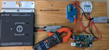
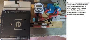
Setup 1.JPGSetup 2.JPG

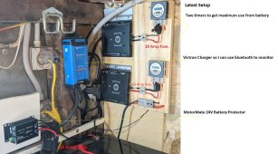
Setup 3.JPG
B
 
Last edited:
Note: Over the last three years I have tested so many combinations of devices you would not believe.
Starting with a computer UPS that 4 different electricians said would not work.
What I have distilled is our best observations, that we have shared, over that time.

OK, so the Micro-Inverter directly connected to battery is still running fine, right?
_Yes that is correct

Assuming ~95% efficiency of your Micro-Inverters, 200WAC out requires 210WDC in which is 8.4A @ 25VDC.
_I don't bother working out efficiency.
_With Micro-Inverters I just add more panels if I need more juice.

Would appreciate it if you could provide your Micro-Inverter model or better yet, tell us what it’s maximum input current rating is…
_Enphase M215 is the main model I use.
_Maximum input current is 10.5A https://www.adelaidesolarsafe.com.au/docs/enphase/Enphase_M215_Micro_inverter.pdf

300WAC out requires 315WDC in or 10.5A @ 30VDC out of your voltage booster.
_Yes that is correct.
_Initially I bought the Boost Converters to "control" the current because articles on DIYSolarForum & other places said connecting directly to the battery would fry the Micro-Inverters.
_After buying 3 boost converters I thought I could replicate the above on all three but I could not get any two adjustments the same.
_I tried about 4 different types of cheaper type Boost Converters (up to about AUD $95) but they all had some sort of issue. (Usually adjustment)
_There is certainty in my mind that there may either be a more expensive type of Boost Converter out there that will do the job (I have seen some) or a much better sub $100 Boost Converter will soon be available.
_In the end I tried connecting one Micro-inverter directly and it worked. Talk about the hard way!

And if the booster has efficiency of ~95%, the booster is taking input power of 332W = 13.3A @ 25VDC from the battery.
_Your calculations are correct.
_I don't bother working out efficiency. I did it a few times but I don't see the point.
_With Micro-Inverters I just add more panels if I need more juice.

Sounds like you are either using two different Micro-inverters or perhaps you are pumping the battery voltage up to higher than 32VDC???
_There are 4 different types of micro-inverters on our roof 3 x Enphase 1 x SunnyBoy
_M215's are all I have used for no particular reason. (I got a box of 40 of these M215's for $30 Each brand new)

So you’ve been running both direct-connect and through-booster configurations for over two years now and both have worked fine over that period of continuous use.
_That is correct

Since the booster was not needed, adds complexity, and reduces net efficiency, you’re going to convert that boosted setup to direct-connect as well.
_I did not say "reduces net efficiency" but the Boost Converter runs relatively warm. Add in the reasons outlined above & you can see our train of thought.
_Adjusting the current crop of Boost converters is too hard for a lot of people and more mistakes can be made.
_With our setup of two timers per battery I can run one Micro Inverter for 14 hours. Then if the battery deteriorates I can set the second timer to turn off inside the point where our battery protector kicks in.
_This gives us 3 levels of "protection" ...A. The Timer(s) ...B. The Victron or MotorMate Battery Protector ...C. The BMS on the battery itself

Have I understood all of that correctly?
Hopefully this question is answered.

Our mantra has always been:
To make it simple (using off the shelf parts) so any one can contribute to reducing global warming.
(One battery dramatically increases Energy Independence.)
Keep the charging & battery side separate to allow for many technologies.
Have the Inverter side separate so you can change Inverter & Battery Protector to whatever you want of fits.
This is the reason my wife & I went this way as our contribution to the environment so we could bring many others with us.
We could have bought a Tesla Battery but most people cannot afford that & are severely inhibited whilst trying to contribute.
Our system is designed to use the inevitable flood of batteries from electric cars.
Our intent was to break the Electric Car batteries down to 24Volt size initially.
If you want to start at 48Volt batteries it will save me some time.
M215's have a maximum of 45V - IQ7Plus can go as high as 60V.
I am expecting a second hand electric car battery this year. I will get an IQ7Plus & test that first.

View attachment 143092View attachment 143093View attachment 143094
Thank you for taking the time to contribute this detailed post. I greatly appreciate and have been planning to follow in your footsteps without knowing it.

I have a spare 250Wx2 dual Microinverter that I am going to hook up direct connect to my 25V LiFePO4 battery the way you have.

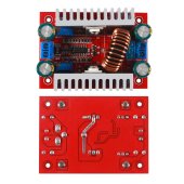
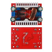
In addition, I already bought a few of the cheapo DCDC boosters similar to the one shown in your picture:

E62A511E-D21F-42F2-B6E2-66023B69FD93.jpeg

I also have a spare 250W single Microinverter which I will hook through one or more of these DC-DC converters, the goal being to throttle output back from a full 250W using the current limit potentiometer, as you are doing but state was troublesome.

It won’t be until late this year but I will report back on whether I had any better luck than you.

The attraction of using the DC-DC boosters, if they can be made to work, is dialing-in a preprogrammed output level rather than letting the Microinverters run full tilt…
 
Boost, or buck?
If buck falls out of regulation, output could be zero or battery voltage.
If boost falls out, voltage can keep rising and blow connected equipment.

(I recently read a non-technical recommendation against charging cell phone from car. Likely the issue being a bad USB charger that passes through full 12 ~ 14V. I've been using whatever model adapter; maybe I should look for name brand or implement crowbar. We should also have charger cord with only power no data, for malware protection when using unknown chargers.)
 
Boost, or buck?
Assume you are addressing that question to me?

I’m planning to use DCDC boost converters fed by a 24VDC LiFePO4 battery, primarily for the controllable constant current output.
If buck falls out of regulation, output could be zero or battery voltage.
If boost falls out, voltage can keep rising and blow connected equipment.
Not planning to buck and will likely limit boost to the minimum of +2V. Since the 8S LiFePO4 can change up to a max of 28.8VDC, will probably set boost voltage at 32VDC. If you are stating that a failure mode for boost DCDC converters is for output voltage to rise uncontrollably past max input voltage of the Microinverter (55VDC in my case), I’d like to learn more…
(I recently read a non-technical recommendation against charging cell phone from car. Likely the issue being a bad USB charger that passes through full 12 ~ 14V. I've been using whatever model adapter; maybe I should look for name brand or implement crowbar. We should also have charger cord with only power no data, for malware protection when using unknown chargers.)
Slightly off-topic for the thread, but if you have any more insight into what can happen when a boost converters ‘falls out of regulation’ I’d like to learn more.

I’m using a couple old otherwise getting trashed Microinverters, so potential damage to the Microinverters is much less important than safety.

On the other hand, if I can avoid having my experiment go up in smoke on day 1, I’d like to try ;).

Debating between direct-connect to battery and programmable connect through a DC-DC boost converter (exactly the same 2 configurations the OP is using). Will likely try both unless there is a clear reason one approach is clearly more likely to cause premature wear / damage to a Microinverter…
 
Note: Over the last three years I have tested so many combinations of devices you would not believe.
Starting with a computer UPS that 4 different electricians said would not work.
What I have distilled is our best observations, that we have shared, over that time.

OK, so the Micro-Inverter directly connected to battery is still running fine, right?
_Yes that is correct

Assuming ~95% efficiency of your Micro-Inverters, 200WAC out requires 210WDC in which is 8.4A @ 25VDC.
_I don't bother working out efficiency.
_With Micro-Inverters I just add more panels if I need more juice.

Would appreciate it if you could provide your Micro-Inverter model or better yet, tell us what it’s maximum input current rating is…
_Enphase M215 is the main model I use.
_Maximum input current is 10.5A https://www.adelaidesolarsafe.com.au/docs/enphase/Enphase_M215_Micro_inverter.pdf

300WAC out requires 315WDC in or 10.5A @ 30VDC out of your voltage booster.
_Yes that is correct.
_Initially I bought the Boost Converters to "control" the current because articles on DIYSolarForum & other places said connecting directly to the battery would fry the Micro-Inverters.
_After buying 3 boost converters I thought I could replicate the above on all three but I could not get any two adjustments the same.
_I tried about 4 different types of cheaper type Boost Converters (up to about AUD $95) but they all had some sort of issue. (Usually adjustment)
_There is certainty in my mind that there may either be a more expensive type of Boost Converter out there that will do the job (I have seen some) or a much better sub $100 Boost Converter will soon be available.
_In the end I tried connecting one Micro-inverter directly and it worked. Talk about the hard way!

And if the booster has efficiency of ~95%, the booster is taking input power of 332W = 13.3A @ 25VDC from the battery.
_Your calculations are correct.
_I don't bother working out efficiency. I did it a few times but I don't see the point.
_With Micro-Inverters I just add more panels if I need more juice.

Sounds like you are either using two different Micro-inverters or perhaps you are pumping the battery voltage up to higher than 32VDC???
_There are 4 different types of micro-inverters on our roof 3 x Enphase 1 x SunnyBoy
_M215's are all I have used for no particular reason. (I got a box of 40 of these M215's for $30 Each brand new)

So you’ve been running both direct-connect and through-booster configurations for over two years now and both have worked fine over that period of continuous use.
_That is correct

Since the booster was not needed, adds complexity, and reduces net efficiency, you’re going to convert that boosted setup to direct-connect as well.
_I did not say "reduces net efficiency" but the Boost Converter runs relatively warm. Add in the reasons outlined above & you can see our train of thought.
_Adjusting the current crop of Boost converters is too hard for a lot of people and more mistakes can be made.
_With our setup of two timers per battery I can run one Micro Inverter for 14 hours. Then if the battery deteriorates I can set the second timer to turn off inside the point where our battery protector kicks in.
_This gives us 3 levels of "protection" ...A. The Timer(s) ...B. The Victron or MotorMate Battery Protector ...C. The BMS on the battery itself

Have I understood all of that correctly?
Hopefully this question is answered.

Our mantra has always been:
To make it simple (using off the shelf parts) so any one can contribute to reducing global warming.
(One battery dramatically increases Energy Independence.)
Keep the charging & battery side separate to allow for many technologies.
Have the Inverter side separate so you can change Inverter & Battery Protector to whatever you want of fits.
This is the reason my wife & I went this way as our contribution to the environment so we could bring many others with us.
We could have bought a Tesla Battery but most people cannot afford that & are severely inhibited whilst trying to contribute.
Our system is designed to use the inevitable flood of batteries from electric cars.
Our intent was to break the Electric Car batteries down to 24Volt size initially.
If you want to start at 48Volt batteries it will save me some time.
M215's have a maximum of 45V - IQ7Plus can go as high as 60V.
I am expecting a second hand electric car battery this year. I will get an IQ7Plus & test that first.

View attachment 143092View attachment 143093View attachment 143094
Sorry, one more quick question for you about battery voltage:

All of your results after 2 years of continuous use have been with a 24VDC battery, correct?

You experimented with DC-DC boost up to 32V and maybe even close to 48VDC but you have not yet tested anything running directly off of a 48VDC battery, correct?

You are planning to get an EV battery and to break the cells down to 24VDC cells/batteries, correct, or will you now plan to go straight to 48V cells/batteries?

Since you have been running the one Enphase M215 off of one of those cheap DCDC boosters for over two years now, I’d appreciate to know the boost voltage used over the majority of that time - 32VDC?
 
(I recently read a non-technical recommendation against charging cell phone from car. Likely the issue being a bad USB charger that passes through full 12 ~ 14V. I've been using whatever model adapter; maybe I should look for name brand or implement crowbar. We should also have charger cord with only power no data, for malware protection when using unknown chargers.)

This can be mitigated by using an isolated converter. Inverter to AC to AC USB power supply will be guaranteed isolated. DC DC should be presumed non isolated if not stated in specs or chinesium but for this power level a flyback or other isolated topology would probably be not a huge increase in cost. Maybe another mitigation would be to charge through a DC-DC battery UPS, that will provide a few isolation layers to blow through.

There are also programmable eFuses designed for protecting these classes of devices, that can provide over voltage protection. However may be slight judgment call to pick a voltage with variable voltage USB charging. I guess if you pick 9V most phones would be fine.

Charger only with no data won’t work without degrading performance. The USB2 data pins are needed for USB PD
 
Note: Over the last three years I have tested so many combinations of devices you would not believe.
Starting with a computer UPS that 4 different electricians said would not work.
What I have distilled is our best observations, that we have shared, over that time.

OK, so the Micro-Inverter directly connected to battery is still running fine, right?
_Yes that is correct

Assuming ~95% efficiency of your Micro-Inverters, 200WAC out requires 210WDC in which is 8.4A @ 25VDC.
_I don't bother working out efficiency.
_With Micro-Inverters I just add more panels if I need more juice.

Would appreciate it if you could provide your Micro-Inverter model or better yet, tell us what it’s maximum input current rating is…
_Enphase M215 is the main model I use.
_Maximum input current is 10.5A https://www.adelaidesolarsafe.com.au/docs/enphase/Enphase_M215_Micro_inverter.pdf

300WAC out requires 315WDC in or 10.5A @ 30VDC out of your voltage booster.
_Yes that is correct.
_Initially I bought the Boost Converters to "control" the current because articles on DIYSolarForum & other places said connecting directly to the battery would fry the Micro-Inverters.
_After buying 3 boost converters I thought I could replicate the above on all three but I could not get any two adjustments the same.
_I tried about 4 different types of cheaper type Boost Converters (up to about AUD $95) but they all had some sort of issue. (Usually adjustment)
_There is certainty in my mind that there may either be a more expensive type of Boost Converter out there that will do the job (I have seen some) or a much better sub $100 Boost Converter will soon be available.
_In the end I tried connecting one Micro-inverter directly and it worked. Talk about the hard way!

And if the booster has efficiency of ~95%, the booster is taking input power of 332W = 13.3A @ 25VDC from the battery.
_Your calculations are correct.
_I don't bother working out efficiency. I did it a few times but I don't see the point.
_With Micro-Inverters I just add more panels if I need more juice.

Sounds like you are either using two different Micro-inverters or perhaps you are pumping the battery voltage up to higher than 32VDC???
_There are 4 different types of micro-inverters on our roof 3 x Enphase 1 x SunnyBoy
_M215's are all I have used for no particular reason. (I got a box of 40 of these M215's for $30 Each brand new)

So you’ve been running both direct-connect and through-booster configurations for over two years now and both have worked fine over that period of continuous use.
_That is correct

Since the booster was not needed, adds complexity, and reduces net efficiency, you’re going to convert that boosted setup to direct-connect as well.
_I did not say "reduces net efficiency" but the Boost Converter runs relatively warm. Add in the reasons outlined above & you can see our train of thought.
_Adjusting the current crop of Boost converters is too hard for a lot of people and more mistakes can be made.
_With our setup of two timers per battery I can run one Micro Inverter for 14 hours. Then if the battery deteriorates I can set the second timer to turn off inside the point where our battery protector kicks in.
_This gives us 3 levels of "protection" ...A. The Timer(s) ...B. The Victron or MotorMate Battery Protector ...C. The BMS on the battery itself

Have I understood all of that correctly?
Hopefully this question is answered.

Our mantra has always been:
To make it simple (using off the shelf parts) so any one can contribute to reducing global warming.
(One battery dramatically increases Energy Independence.)
Keep the charging & battery side separate to allow for many technologies.
Have the Inverter side separate so you can change Inverter & Battery Protector to whatever you want of fits.
This is the reason my wife & I went this way as our contribution to the environment so we could bring many others with us.
We could have bought a Tesla Battery but most people cannot afford that & are severely inhibited whilst trying to contribute.
Our system is designed to use the inevitable flood of batteries from electric cars.
Our intent was to break the Electric Car batteries down to 24Volt size initially.
If you want to start at 48Volt batteries it will save me some time.
M215's have a maximum of 45V - IQ7Plus can go as high as 60V.
I am expecting a second hand electric car battery this year. I will get an IQ7Plus & test that first.

View attachment 143092View attachment 143093View attachment 143094
I'm apologize for coming back with all these additional questions, but I've been carefully reviewing the detailed pictures you attached and just want to assure I've got the details correct:

Initial Setup: Victron Battery Connect inline (and no other relay) - Battery Connect disconnected from overcurrent often when not necessary - do you know what the overcurrent limit of the Battery Connect was?

Second Setup: Victron Battery Connect controlling inline Relay: - what was the amperage rating of the DC relay you used?

Latest Setup: MotorMate 24V Battery Protector inline (and no other relay): what is the overcurrent limit of the MotorMate and can you program the low-voltage limit where the MotorMate disconnects the system or is it fixed?

Other than the use of the MotorMate, are there and DC fuses or breakers in your Latest Setup other than whatever fuse you are using for each of your 24V batteries? Oh, wait, I see an inline blade fuse holder connected to the MotorMate - what size fuse are you using there and is that the only DC fuse outside of the batteries?

Thanks in advance.
 
If you are stating that a failure mode for boost DCDC converters is for output voltage to rise uncontrollably past max input voltage of the Microinverter (55VDC in my case), I’d like to learn more…

Slightly off-topic for the thread, but if you have any more insight into what can happen when a boost converters ‘falls out of regulation’ I’d like to learn more.

The chips I've worked with have external voltage divider fed back to sense pin. Failure in that path means it keeps boosting without limit.
One design was switchable by relay, and design had open circuit between two ratios, instead of a ratio hard-wired with resistors and another resistor switched in parallel. It went over-voltage and killed the load.

Battery --> 120VAC --> factory charger was recommended in the article. I prefer compact DC/DC, but want failsafe.


Charger only with no data won’t work without degrading performance. The USB2 data pins are needed for USB PD

Which is my preference. Gentle charge.
There are USB sources everywhere, and those have been used to hack a smart phone and drain bank accounts.
 
Battery --> 120VAC --> factory charger was recommended in the article. I prefer compact DC/DC, but want failsafe.
There is also using a power bank all the time.

Even with flyback boost topology could get you, I think. With the boost going berserk.

Buck with flyback would work for 5V and 9V charging wrt being failsafe & not putting 12V+ on it
 
The chips I've worked with have external voltage divider fed back to sense pin. Failure in that path means it keeps boosting without limit.

One design was switchable by relay, and design had open circuit between two ratios, instead of a ratio hard-wired with resistors and another resistor switched in parallel. It went over-voltage and killed the load.
These are the cheapo DCDC boosters I’m going to be experimenting with:

DAE72559-A796-4593-84DD-ED60C7879F19.jpeg
They have two potentiometers hard-wired in for control, one to set current limit and one to set voltage limit,

Any idea whether a design using a wired-in (settable) resistor can suffer from the uncontrolled boost you experienced?

I suppose adding a monitor circuit to shut everything down if any boost voltage exceeds 150% or even 125% of target wouldn’t be the end of the world…
Battery --> 120VAC --> factory charger was recommended in the article. I prefer compact DC/DC, but want failsafe.
You are still talking about charging a phone, or is that somehow relative to the thread topic?
Which is my preference. Gentle charge.
There are USB sources everywhere, and those have been used to hack a smart phone and drain bank accounts.
Sounds like more phone charging stuff. Appreciate any input you have on how to prevent against the possibility of a DC-DC boost converter exceeding the maximum input voltage rating of a Microinverter, but the subject of charging mobile phones or any other electronics for that matter is really not relevant to the subject of this thread…
 
Appreciate any input you have on how to prevent against the possibility of a DC-DC boost converter exceeding the maximum input voltage rating of a Microinverter
I think a DC overvoltage protection circuit, that disconnects when the voltage is out of spec, would be sufficient. This is basically eFuse or FET based BMS functionality. eFuse directly does this. BMS has voltage thresholds that will disconnect
 
I think a DC overvoltage protection circuit, that disconnects when the voltage is out of spec, would be sufficient. This is basically eFuse or FET based BMS functionality. eFuse directly does this. BMS has voltage thresholds that will disconnect
For my setup, probably easier to just monitor boost voltage directly with my PLC and shut everything down if I see anything unexpected. In fact, I could use a diode bank feeding a simple RC bleeder circuit to monitor all boosted voltages in parallel (max voltage circuit).

Sounds like a good thing to plan for and unless output voltage can spike from desired ~32VDC to >55VDC within a matter of milliseconds, should provide solid protection.

I can also add large caps on all DC boosted inputs to slow down transients including excessive voltage overshoots.

Will also slow down the delay for ramp-up and ramp-down when boosted DC input is switched on or off, but slower ramp-up is a non-issue, and an active pull-down resistor than only drains when input has been shut off can speed up rampdown as much as needed…

This sounds like a solvable issue.
 
They have two potentiometers hard-wired in for control, one to set current limit and one to set voltage limit,

Any idea whether a design using a wired-in (settable) resistor can suffer from the uncontrolled boost you experienced?

Worn potentiometers may go high value. You can use fixed resistors plus potentiometer to limit adjustment range and get finer adjustment.
For your application, you may actually want wattage control. Which a CV/CC supply with at least one adjustable would provide.

I suppose adding a monitor circuit to shut everything down if any boost voltage exceeds 150% or even 125% of target wouldn’t be the end of the world…

I was thinking zener or similar activating shutdown. A redundant feedback path.

You are still talking about charging a phone, or is that somehow relative to the thread topic?

Faulty buck was likely the idea behind phone charger article. Same issue to be considered for thread topic; likely full input voltage is OK which is why I suggested buck, as an alternative to boost which could have a failure mode.

For my setup, probably easier to just monitor boost voltage directly with my PLC and shut everything down if I see anything unexpected. In fact, I could use a diode bank feeding a simple RC bleeder circuit to monitor all boosted voltages in parallel (max voltage circuit).

I prefer continuous analog monitoring over polling or even interrupts. What I've designed before is limit set by DAC, and comparator (I used op-amp, but be careful to understand issues with them) to detect and turn off.

Sounds like a good thing to plan for and unless output voltage can spike from desired ~32VDC to >55VDC within a matter of milliseconds, should provide solid protection.

Under no-load it can, and I've seen it (the aftermath, not in real time.) I think an SPDT relay, break before make, may have done that. (but I could be mistaken.)
 
Worn potentiometers may go high value. You can use fixed resistors plus potentiometer to limit adjustment range and get finer adjustment.
Appreciate this extensive post - very helpful.

I’m ready to replace the potentiometers with fixed resistors once I determine the resistance value needed. There are also these configurable resistance networks that are modestly priced. So if eliminating the potentiometers would reduce the risk of voltage overshoot by 90%, sounds like the thing to do…
For your application, you may actually want wattage control. Which a CV/CC supply with at least one adjustable would provide.
Yes, I’m using the DC-DC booster to preprogram wattage. Setting both boost voltage (probably to ~32VDC) and current (to ~target W / V_boost).

If both of those potentiometers (one for CV limit and one for CC limit) is a risk factor, I can replace them both.
I was thinking zener or similar activating shutdown. A redundant feedback path.
So a zener that camps output voltage to below the danger zone of the Microinverter - fantastic suggestion! For a target max voltage of 40V-50VDC, do Zeners with breakdown voltage in that range exist or do you need to wire up a slightly more complicated circuit (multiple zeners in series or whatever).

I suppose I should check that the DC-DC boosters don’t already integrate similar overvoltage protection…
I prefer continuous analog monitoring over polling or even interrupts. What I've designed before is limit set by DAC, and comparator (I used op-amp, but be careful to understand issues with them) to detect and turn off.
Yeah, brains are fantastic but analog feedback can’t go blue screen ;).

For my application, I don’t need any control over overvoltage setting. It’s fixed by the Microinverter specs at 55VDV. So any hardwired-circuit that prevents voltage from ever exceeding that limit or even some margin below that would work fine.

Which makes me wonder why a similar Zener-Diode-based protection circuit is not used to protect Microinverters from the possibility of Voc exceeding max voltage limits???
Under no-load it can, and I've seen it (the aftermath, not in real time.) I think an SPDT relay, break before make, may have done that. (but I could be mistaken.)
I should never have no-load (Microinverters will always be on when DC-DC booster is boosting) and I can easily assure a delay between Microinverter first connecting to grid and DC-DC boaster getting turned on…
 
Appreciate this extensive post - very helpful.

I’m ready to replace the potentiometers with fixed resistors once I determine the resistance value needed. There are also these configurable resistance networks that are modestly priced. So if eliminating the potentiometers would reduce the risk of voltage overshoot by 90%, sounds like the thing to do…

Or keep them for trim, and add fixed resistors in series and/or parallel to design the adjustment range.

So a zener that camps output voltage to below the danger zone of the Microinverter - fantastic suggestion! For a target max voltage of 40V-50VDC, do Zeners with breakdown voltage in that range exist or do you need to wire up a slightly more complicated circuit (multiple zeners in series or whatever).

Zeners are available in a wide range. They have a gradual diode curve, so typically biased with some controlled current flow to get voltage reference.
I've used a series string of various voltages + shorting plug and resistor to generate 14.5 kV node from a 15kV supply. (After previously using two supplies, and the transient delta voltage fried the electrodes. Research lab stuff, but zeners are old hat.)

I should never have no-load (Microinverters will always be on when DC-DC booster is boosting) and I can easily assure a delay between Microinverter first connecting to grid and DC-DC boaster getting turned on…

Microinverters will be off and no-load while waiting to qualify AC, or if power limiting.
 
Or keep them for trim, and add fixed resistors in series and/or parallel to design the adjustment range.
Parallel is an interesting idea…
Zeners are available in a wide range. They have a gradual diode curve, so typically biased with some controlled current flow to get voltage reference.
I've used a series string of various voltages + shorting plug and resistor to generate 14.5 kV node from a 15kV supply. (After previously using two supplies, and the transient delta voltage fried the electrodes. Research lab stuff, but zeners are old hat.)
Will do, thanks.
Microinverters will be off and no-load while waiting to qualify AC, or if power limiting.
Yes, but I can delay turn-on of DCDC boosters until after Microinverters are on grid and reporting 0W of output power…
 
For a target max voltage of 40V-50VDC, do Zeners with breakdown voltage in that range exist or do you need to wire up a slightly more complicated circuit (multiple zeners in series or whatever).

There might be a passive circuit with zener and resistor to drive a shutdown pin (but might oscillate.)

You can use a couple volt zener and resistor to make a reference voltage, compare that to a resistor divider, have latching feedback circuit. I've used diodes and resistors to get latching function from an op-amp. Have to work out power-up and reset mechanism. Mine used a DAC and sent interrupt, so uP could read state and command DAC far enough to reset.

There turned out to be multiple issues with using op-amp as comparator, but I did find a way to make it perform well enough. Analog Devices has papers on the topic.
 
Thank you for taking the time to contribute this detailed post. I greatly appreciate and have been planning to follow in your footsteps without knowing it.

I have a spare 250Wx2 dual Microinverter that I am going to hook up direct connect to my 25V LiFePO4 battery the way you have.

In addition, I already bought a few of the cheapo DCDC boosters similar to the one shown in your picture:

View attachment 143142

I also have a spare 250W single Microinverter which I will hook through one or more of these DC-DC converters, the goal being to throttle output back from a full 250W using the current limit potentiometer, as you are doing but state was troublesome.

It won’t be until late this year but I will report back on whether I had any better luck than you.

The attraction of using the DC-DC boosters, if they can be made to work, is dialing-in a preprogrammed output level rather than letting the Microinverters run full tilt…
Thank you for taking the time to contribute this detailed post. I greatly appreciate and have been planning to follow in your footsteps without knowing it.
_Anything that reduces Greenhouse gasses I am for it!

I have a spare 250Wx2 dual Microinverter that I am going to hook up direct connect to my 25V LiFePO4 battery the way you have.
_Sounds Good. Not sure what brand or type you have....So...Do one side first. That way you might get 2 chances is something goes wrong.
_Start with the lowest voltage you can first & work up from there.

In addition, I already bought a few of the cheapo DCDC boosters similar to the one shown in your picture:
_Pretty sure I have tried something very similar.

I also have a spare 250W single Microinverter which I will hook through one or more of these DC-DC converters, the goal being to throttle output back from a full 250W using the current limit potentiometer, as you are doing but state was troublesome.
_IMPORTANT ...My observations - Because of the MPPT the micro-inverter takes a fair while to start. So you have to have patience. Quite often mine restart at least once.
_So the micro inverter, from cold, will start to produce.
_So there is no slower start like you would get with the sun.
_The micro inverter decides this is a bit strange and cuts you off. (Because it has gone from cold to full production IMO)
_The second time around things have warmed up and the micro inverter is good to go. (Please let me know if you observe similar)
_When adjusting the buck converter you will find the micro inverter "trips" at various times and restarts.
_I think it is better to adjust the buck converter using some sort of separate, constant load, at the right amperage, first, as the MPPT makes it really hard to adjust the potentiometers.


It won’t be until late this year but I will report back on whether I had any better luck than you.
_Looking forward to it.

The attraction of using the DC-DC boosters, if they can be made to work, is dialing-in a preprogrammed output level rather than letting the Microinverters run full tilt…
_I have read articles where people are pumping out more than 350W @ 240AC and running voltages higher than the maximum voltage.
_The Enphase inverters seem to be able to take a beating.
_At 24V (28.8V when battery full) the inverters pump out 226W @240VAC each which is not much above the 215W Rated Output Power
 
I'm apologize for coming back with all these additional questions, but I've been carefully reviewing the detailed pictures you attached and just want to assure I've got the details correct:

Initial Setup: Victron Battery Connect inline (and no other relay) - Battery Connect disconnected from overcurrent often when not necessary - do you know what the overcurrent limit of the Battery Connect was?

Second Setup: Victron Battery Connect controlling inline Relay: - what was the amperage rating of the DC relay you used?

Latest Setup: MotorMate 24V Battery Protector inline (and no other relay): what is the overcurrent limit of the MotorMate and can you program the low-voltage limit where the MotorMate disconnects the system or is it fixed?

Other than the use of the MotorMate, are there and DC fuses or breakers in your Latest Setup other than whatever fuse you are using for each of your 24V batteries? Oh, wait, I see an inline blade fuse holder connected to the MotorMate - what size fuse are you using there and is that the only DC fuse outside of the batteries?

Thanks in advance.
I'm apologize for coming back with all these additional questions, but I've been carefully reviewing the detailed pictures you attached and just want to assure I've got the details correct:
_No problem.

Initial Setup: Victron Battery Protector inline (and no other relay) - Battery Connect disconnected from over-current often when not necessary - do you know what the over-current limit of the Battery Connect was?
_No I don't.

Second Setup: Victron Battery Connect controlling inline Relay: - what was the amperage rating of the DC relay you used?
_20Amp

Latest Setup: MotorMate 24V Battery Protector inline (and no other relay): what is the over-current limit of the MotorMate and can you program the low-voltage limit where the MotorMate disconnects the system or is it fixed?
_MotormMate 24V version is rated at 30Amp. https://www.master-instruments.com.au/file/63492/1/Motormate-SBP-12030.pdf
_There are only 3 switched cut out settings 23V 22V 21V. I use 23V.

Other than the use of the MotorMate, are there and DC fuses or breakers in your Latest Setup other than whatever fuse you are using for each of your 24V batteries? Oh, wait, I see an inline blade fuse holder connected to the MotorMate - what size fuse are you using there and is that the only DC fuse outside of the batteries?
_At the MotorMate I use 20A fuse & 10A fuse at each inverter. I have updated picture.
 
Last edited:
Back
Top