You are using an out of date browser. It may not display this or other websites correctly.
You should upgrade or use an alternative browser.
You should upgrade or use an alternative browser.
Melted Wiring in GSL Battery - Any idea what went wrong here?
- Thread starter weirded
- Start date
Batrium states you should do this. I've also done this on all my balancing leads on the JK BMSs I use. Used these fuses in appropriate inline holder: https://www.digikey.com/en/products/detail/optifuse/FCD-3-15A/12090372
If a fault occurs with the balance leads wouldn't it be a short of some kind, and if it is I thought those smaller fuses can't actually interrupt a LifePo4 battery based on their AIC (it's the reason T-class fuses are recommended) - so if the balance leads got shorted wouldn't it just arc over and the power would keep going with the small fuses like that?
Some have said it is needless to add these fuses to balance leads but I am specifically using ceramic fuses which have a 1000A AIC at 250VDC for a small 3.15A fuse.If a fault occurs with the balance leads wouldn't it be a short of some kind, and if it is I thought those smaller fuses can't actually interrupt a LifePo4 battery based on their AIC (it's the reason T-class fuses are recommended) - so if the balance leads got shorted wouldn't it just arc over and the power would keep going with the small fuses like that?
Hm...went back and looked at some pictures I took while exchanging a defect BMS last year on one battery.
Different brand ofc. compared to the OP but...made from the factory to stand on the rubber feet on the back plate and pointing upwards...no sign of leakage though. Cells are then sideways mounted.
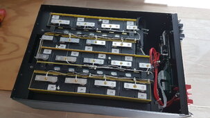
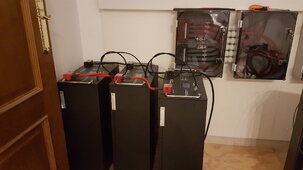
I can ofc. lay them flat on top of each other but that will require a wood "rack" system to be built to carry the weight.
Do not think it is a good idea to just plonk 90kgs per on top of each other with only the 1.5mm steel plates to carry the weight...these are 200ah big size batts.
Or am I overthinking this? Have not inspected them inside since around 08.2022 when I changed the BMS on one unit.
Different brand ofc. compared to the OP but...made from the factory to stand on the rubber feet on the back plate and pointing upwards...no sign of leakage though. Cells are then sideways mounted.


I can ofc. lay them flat on top of each other but that will require a wood "rack" system to be built to carry the weight.
Do not think it is a good idea to just plonk 90kgs per on top of each other with only the 1.5mm steel plates to carry the weight...these are 200ah big size batts.
Or am I overthinking this? Have not inspected them inside since around 08.2022 when I changed the BMS on one unit.
Last edited:
Steve_S
Offgrid Cabineer, N.E. Ontario, Canada
You have been lucky so far, and you can stack those cases - there is no direct pressure transferred to the internals.Hm...went back and looked at some pictures I took while exchanging a defect BMS last year on one battery.
Different brand ofc. compared to the OP but...made from the factory to stand on the rubber feet on the back plate and pointing upwards...no sign of leakage though. Cells are then sideways mounted.
View attachment 187351
View attachment 187352
I can ofc. lay them flat on top of each other but that will require a wood "rack" system to be built to carry the weight.
Do not think it is a good idea to just plonk 90kgs per on top of each other with only the 1.5mm steel plates to carry the weight...these are 200ah big size batts.
Or am I overthinking this? Have not inspected them inside since around 08.2022 when I changed the BMS on one unit.
LFP Prismatics are NOT supposed to be on their sides, Most Manufacturers have that in the specs sheets... IT IS AN INVITATION FOR MURPHY & HIS LAWS.
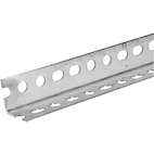
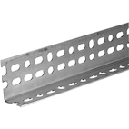
You can also build a Rack using perforated Angle Steel, Box & Flat stock & you can bolt it together.
Box on the back with L Angles making "shelf rails" connected in front @ each corner to L angles as well with the flat stock across the front as bracing the shelf rails. You would not need a "shelf bottom" just enough to support the whole sides of the cases. The thickness of the stock will determine the load handling.
Angle as I describe. Either would work. Box & Flat stock similar to below. Zinc Plated can be painted too BUT must be etched for the paint to stick.
Is that the thickness of the steel used in those Seplos and similar DIY boxes? 16 gauge?the 1.5mm steel plates
@GuyG: Probably around 1.5mm yes. This is a different brand than Seplos though and premade.
As we see from the photos this has been welded - not my favorite. Difficult to repair if a cell craps out.
I have started to build my own this year and will continue to do so in the future. So much better capacity and quality of parts.
The issue for me is that I have 4 of these premades in my system and it will be expensive to change them.
I have no issues with them so far other than crappy BMSs which can't calculate SoC to save their lives.
Earlier threads during the last years on this forum said stacking cells flat sideways was no issues but looking at the pictures from the OP of this thread I started to worry about it.
I might do as Steve mentions and relocate the units to normal horisontal making the cells point upwards. I hate to redo cabling and make a support structure for it though...
If this really IS a problem - stay away from wall hung batteries etc. as the cells will be placed flat horizontally in the chassis.
And ofc. the manual from f.ex. EVE...the paragraph that is listed as to placement and direction...is blank. FRAKKERS!
Starting to think no manufacturer can be fully trusted.
Last edited:
Just an example of earlier threads the last years:
https://diysolarforum.com/threads/lifepo4-on-its-side.5215/
https://diysolarforum.com/threads/lifepo4-on-its-side.5215/
Ironically the OP of that thread had a battery fire since he decided to place the cells facing upwards but the layout of wiring, support of the cells (he stacked cells on top of each other on a type of shelving without adequate support), and general build was not very safe.Just an example of earlier threads the last years:
https://diysolarforum.com/threads/lifepo4-on-its-side.5215/
HughF
New Member
Flexnet + LFP owner here…. The flexnet is a shunt and %SOC tracker, with an aux relay. Nothing more. Bulk current/absorption setpoint + timer/ float setpoint are all set either in the outback inverter, the mppt, or both.
OffGridForGood
Catch, make or grow everything you can.
Interesting - so from your own experience, the OP needed to check the settings, and these could have been wrong in the inverter/charge controller. This could be corrected, without removing the Flexnet shunt, for his new battery installation?Flexnet + LFP owner here…. The flexnet is a shunt and %SOC tracker, with an aux relay. Nothing more. Bulk current/absorption setpoint + timer/ float setpoint are all set either in the outback inverter, the mppt, or both.
weirded
New Member
- Joined
- May 8, 2021
- Messages
- 145
I can’t say I’ve personally confirmed this bad behavior or even believe that the Flexnet does this, but I didn’t really lose any functionality I cared about by ditching it.Interesting - so from your own experience, the OP needed to check the settings, and these could have been wrong in the inverter/charge controller. This could be corrected, without removing the Flexnet shunt, for his new battery installation?
OffGridForGood
Catch, make or grow everything you can.
I expect the more important part of Hugh F post is:I can’t say I’ve personally confirmed this bad behavior or even believe that the Flexnet does this, but I didn’t really lose any functionality I cared about by ditching it.
Hugh is saying the charge controls are set in the Outback or Charge Controller - I am wondering if the settings by default are for Lead-Acid, and need to be changed to suit LFP. After all, if GSL send you new batteries you will want to know For Sure that the charging settings are correct.Bulk current/absorption setpoint + timer/ float setpoint are all set either in the outback inverter, the mppt, or both.
weirded
New Member
- Joined
- May 8, 2021
- Messages
- 145
So the claim made was that these settings can be overridden by the Flexnet. These settings were done according to manufacturer recommendations for these batteries.I expect the more important part of Hugh F post is:
Hugh is saying the charge controls are set in the Outback or Charge Controller - I am wondering if the settings by default are for Lead-Acid, and need to be changed to suit LFP. After all, if GSL send you new batteries you will want to know For Sure that the charging settings are correct.
OffGridForGood
Catch, make or grow everything you can.
We had this statement - Dave being the experienced former tech for the original co supplier of these iirc,According to Dave, there is essentially no way to observe or control this through the Outback software. He has done a number of systems with Outback and these batteries and strongly recommends simply removing the FlexNet.
And we have this statement - from HughThe flexnet is a shunt and %SOC tracker, with an aux relay. Nothing more.
Not that I am doubting Hugh, if the flexnet is not providing any benefit, removal is no big deal. Personnally I sure like the Victron 500A shunt for monitoring SOC - maybe that is an option.
My main concern: if the Flexnet is not capable of changing battery charge settings, then it's removal doesn't solve the original problem.
HughF
New Member
Correct. The Flexnet does not override the voltage setpoints programmed into the mppt and inverter.Interesting - so from your own experience, the OP needed to check the settings, and these could have been wrong in the inverter/charge controller. This could be corrected, without removing the Flexnet shunt, for his new battery installation?
The original outback gear was designed before we had lithium storage, so the charge algorithms are geared for lead acid. They’re fully programmable, but the system has no ability to communicate with modern batteries that have their own bms/shunt.
This presents a problem where the bms is unable to request a reduction/tapering of charge current when entering bypass/balance mode as the cells reach the upper knee. This can cause a runaway condition (ask me how I know).
It also means that without a flexnet, there is no %SOC available on the outback data bus. And thus you can’t start/stop charging (from a genset in my case) on SOC without one.
HughF
New Member
That’s water damage…. I fix flooded pcbs for a living, I recognise that a mile off.Some learnings/updates for those following along:
Battery #1 is actually intact, but can't handle the inrush current of even a single Radian by itself. I managed to boot up the Radians using a bench power supply, and then added the battery. It is able to take a charge and discharge.
Batteries #2 and #3 had the balance wire fires and are going to be replaced under warranty by GSL supposedly.
Battery #4 (the one showing 0 voltage on some of the cells) actually has burnt resistors on the BMS board, so likely suffered a similar over-current issue than the other two. GSL had me measure out all the cells and those all show the same voltage - so likely they are fine. GSL says they will send me a new BMS for this battery.
View attachment 183946
As I learned, this BMS is made by Seplos, and uses passive balancing.
View attachment 183947
I still can't confidently figure out what happened here, but I wonder if one of the batteries shorted out the balance leads, which led to a low-resistance/short on those leads, and if somehow that caused the other batteries to experience a high current condition on the balance leads, as well.
Anybody have a better educated guess here? I can't quite 100% figure it out.
I'm also really nervous about this BMS at this point...
HughF
New Member
There is an option for the flexnet to control charge termination, but not change the charge parameters:
 forum.outbackpower.com
Taken from the above tech note : "If the Enable Charge Termination Control is set to Y, then the inverters will stop the absorb step and will move on to the float step or silent step (if the Float Timer <= the Absorb Timer)."
Charge termination via Flexnet DC - OutBack Power Technologies User Forum
Taken from the above tech note : "If the Enable Charge Termination Control is set to Y, then the inverters will stop the absorb step and will move on to the float step or silent step (if the Float Timer <= the Absorb Timer)."
Hedges
I See Electromagnetic Fields!
- Joined
- Mar 28, 2020
- Messages
- 21,047
I don’t think there’s much legal recourse. I don’t think they have a legal entity in the US.
In the US, I think it legally falls on the importer.


