Thanks, I never thought about it. I will check all my connections, as well as test with the thermal camera of the system while my vacuum is running.
So, I've undertaken an inventory of all my cables and connectors. My fuse box, 50mm^2 cables, lugs, crimpers, fuses, etc. etc. have all come in, but I am still waiting for my battery fuse holders which should arrive Tuesday.
I did a review of all my connections and corrected a few instances of washers in the current path. Many thanks to
@sunshine_eggo as I never thought about distinguishing
metals from
conducting metals before.
I also undertook an inventory of all my cables. Where I could, I cut into the cable, measured the strands with a dial caliper, and calculated the true cross-sectional area. Where I couldn't cut, I went by the manufacturer's spec based on the printing on the cable. I also weighed shorter cables that I couldn't cut. All of the cables turned out to be either copper or tinned copper, no aluminium. Most of the cables are smaller than what they were sold as. I take it there are wide-ranging rounding errors and I found many bad look-up tables online for AWG <-> mm^2 conversions. I even found and corrected an erroneous value on the American Wire Gauge Wikipedia page. So lemme say, this is incredibly illuminating and brings me joy!
As a baseline before upgrading all my cables, I ran my vacuum for six minutes today, and taking a thermal image review of the components. For visual reference, the setup in view is this:
https://diysolarforum.com/threads/2kw-garage-power-supply.75973/
Then, after I crimp and connect the new fuses and better cables, and throw away the bad circuit breaker, I can test again and see how the thermal character changes.
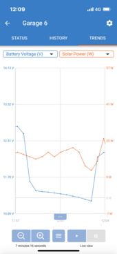
Approx. 6 minutes voltage drop shown for a run of about 1.7kW AC through the inverter.
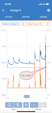
The six minute run seems to put the battery SOC back to about eight (sometimes cloudy and non-producing) days ago. It's February, I think this is tolerable for me and my planned use of the system. It's for LED lighting, occasional use of the shop-vac and power tools.
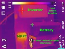
System overview and thermal baseline. The ambient temperature is about 5C. The charger is charging around 1A.
You can compare this picture with
https://diysolarforum.com/attachments/panel-above-jpg.186685/
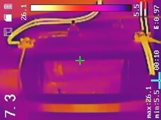
After running the test, the battery. Showing some warmed terminals and cables.
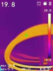
Close-up of the negative battery cable pair. It heated to 20C.
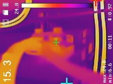
Close-up of the cheap battery terminal and hex bolts. 15C.
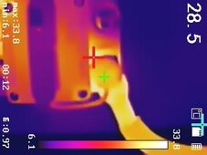
The positive battery cables lead into the cheap circuit breaker input.
Oops, that's the rubber hat I measured! Well it is 29C. The lug must be high 20s, low 30s Celsius.
The circuit breaker body at the point of the red
+ overlay symbol, is 34C.
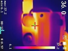
On the other side of the cheap circuit breaker, 36C on the little terminal.
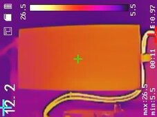
Overview of the inverter body (12C) with the input cables illuminated (high 20s Celsius)
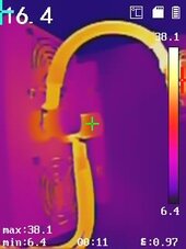
The set of cables coming into the inverter. The green + is on the negative inverter input terminal.
The cables are in the upper-20s - mid-30s Celsius.
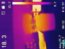
Real close-up of the positive inverter terminal. You can see the conductor part is cool, 18C.
The cable lug (red +) is 26C.
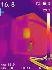
Here is the inverter output and control panel. Interestingly, there is a little warm point (30C) on the face.
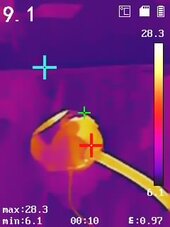
And finally, my shop vac looking like 28C. Just so you get the visceral picture, human body temperature is 37C so these things are slightly warm, not hot.
My Summary
| Cable | My approximation or measurement of cross-sectional area | My assessment |
| Cheap battery terminals | not undertaken | Performance better than expected. I have heavier duty ones now however. |
| Battery output cables as a pair | 16.8 mm^2 x2 = 33.6mm^2 | Get too hot, 20C in six minutes |
| From cheap circuit breaker to inverter (positive side) | 33.6 mm^2 | Same spec as above, it gets too hot |
| Cheap circuit breaker | not undertaken | Clearly inadequate, as multiple people have pointed out already. |
| Inverter | N/A | Seems OK. Will look into the warm point on the face. |
| AC wiring and components | 1.5mm^2 flexible copper | AC system seems adequate.
The USB controller may be drawing more energy than I expected. But, it was running USB lighting at the time. Will check again. |
| Battery to inverter, new cables | 50mm^2 | TBD |
| New heavy brass terminals with M10 bolt | Stamped with "300-800A" | TBD |


