tigerwillow1
Solar Enthusiast
- Joined
- Sep 20, 2021
- Messages
- 194
(Part 1 of 3)
This is a report on the design, construction, and to a limited extent operation of the Seplos 6.9 kWh LiFePO4 Mason DIY kit. Why limited? There is no exhaustive testing, long-term information, information on data connection with an inverter, and I'm not equipped to make measurements of cell internal resistance or good load testing. Other users have better information on operation of the Seplos BMS that I do. I sense there is not a lot of forum interest in this kit, but there is a lot of interest in the Mason kit for the 280 AH cells, and would think a lot of the design items would carry over to the 280 AH kit.
I would have preferred to make a full DIY battery, but decided against it because of wanting a reasonably nice steel case, and not wanting the hassle of sourcing parts like correct plastic and foam for around the cells. The Mason kit completely addresses these issues. I have fairly good prior experience with electronics and PV systems, and no experience whatsoever with LiFePO4 batteries. Pretty much everything I know about LiFePO4 at this point is from the diysolar forum and working with the Mason kits. Last year, Seplos offered a $1,000 promotional price for these Mason kits (about $1,500 shipped to USA), which was my main reason for going with them. A second reason was being able to assemble it myself. After the promotion period the price without shipping rose to $1,600. Today there's no price posted on the web site. I bought 3 of the Masons.
QUICK SUMMARY
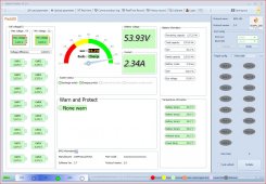
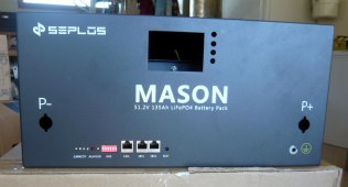
The 6.9 kWh Mason battery is built using sixteen 135 Ah cells and a 100 amp Seplos BMS. The design and construction of the metal case is superb. The self-adhesive insulating sheets and foam dividers look to be very good high-end choices. Printed circuit boards for the BMS connections to the individual cells eliminate the rats nest of wires. There are 4 temp sensors. The battery can be monitored with its panel display or PC app using an RS485 connection and RS485-to-USB adapter. The completed battery weighs about 121 pounds, 96 pounds for the cells, and 25 pounds for the case and BMS. The steel thickness of the case is about 0.05", in the 16 to 18 gauge range. The cells were well packed and arrived with a ~40% SOC, their no load voltages within a few millivolts. I have no reason to suspect that they are not well matched grade A cells. While not a rack mount case, it does fit between the rack uprights to support it with a shelf. I do have some criticisms, explained below.
HIGHLIGHTS
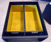
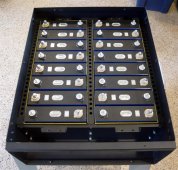
-Very nice case, superb metal work, cell compression provided via foam dividers. Seplos makes nice cases!
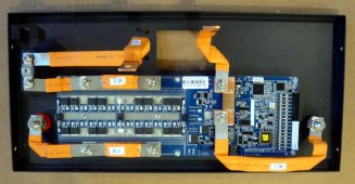
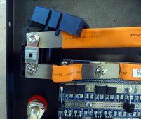
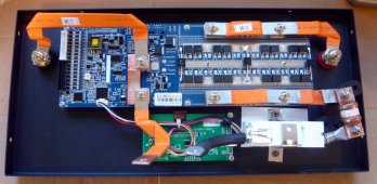
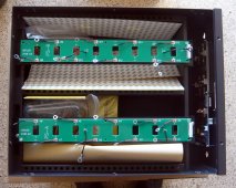
-Very nice busbars for BMS power connections. Made of laminated copper layers, plated, rigid where connections are made and flexible in-between.
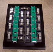
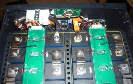
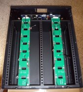
-BMS connections to individual cells made via PC boards, resulting in very neat wiring.
-Adequate build directions translated well to English. They're not Heathkit style hand-holding directions, but totally sufficient to get the job done.
-No missing parts.
LOWLIGHTS/SHORTCOMINGS (detailed below)
-Awful communication about shipping process and progress.
-No mechanical shutoff.
-Questionable internal fuse.
-Not so good power connectors on the panel (The other Mason kits use a different connector).
SHIPPING PROCESS AND COMMUNICATION
For shipping to USA, Seplos turns the package over to a forwarder for the ocean shipping, then (in my case) over to Fedex freight for delivery inside the states. None of this is communicated up front, and the process becomes (1) Send your money, (2) Hope, and (3) About 3 to 4 months later you will get a call from Fedex to arrange delivery (which I and other buyers did). Instead of simply explaining this, Seplos provided misleading info for my shipping enquires that left me thinking for about a month I'd never see the Masons. IMO if they want to succeed in the USA market they need to find a way for someone who speaks good English to provide correct shipping process and status info, or establish a USA based distributor.
NO MECHANICAL SHUTOFF
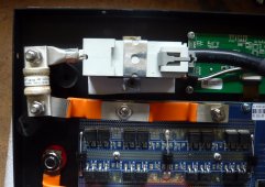
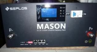
This is definitely opinion. After all, lead acid batteries don't have a shutoff. I want to be sure that the battery is really off when making connections. The BMS can be commanded to shut off the power terminals. My distrust of this arrangement was confirmed a few times when it turned itself on while I was making a connection or doing something with the RS485 interface (I didn't spend time to drill down on this). My response was to add a 125 amp circuit breaker to use as a shutoff. It's in series with a 100 amp fuse, so in theory anyway, the breaker should never trip.
QUESTIONABLE INTERNAL FUSE
The standard fuse is a 150 amp MIDI fuse, its spec sheet listing the "breaking capacity" at 1,000 amps. I do not have fuse expertise. Based on info from the forum I concluded this is not adequate and replaced it with a 100 amp class-T fuse. 100 amps should be sufficient for my PV system, maybe not for a different system. I want the fuse to blow before the 125 amp breaker, which has a lower AIC rating. While a 100 amp fuse is not adequate for the 100 amp max output of the battery, it is adequate for my weaker link of inverter and charger, which should never push or pull more than 80 amps. If I do get nuisance blowing of the fuse, the standoffs I used to mount it can be adjusted to accommodate the physically larger class-T fuses over 100 amps.
NOT SO GOOD POWER CONNECTORS
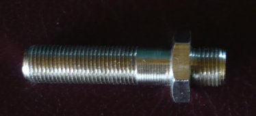
The power connectors use nice heavy fine pitch 10mm studs. That's the good part. There are 2 bad parts: (1) The studs are too short for the lug thickness on my 2/0 cables. Only 2 or 3 threads are engaged by the tightening nut. (2) The nuts are meant to be hand-tightened, which is not good enough for me. When using pliers, I spun the plastic cover on the metal nut. I solved this by flipping the stud and using a hex nut for the battery cable connection. When flipped, the stud length is more than sufficient for the battery cable, and just long enough for the BMS busbar connection inside the case.
ASSEMBLY NOTES
You absolutely need a 1/4 inch torque wrench and 10 mm socket for the cell connections. Some of the internal components are shipped fastened inside the case. The screws used to attach these parts for shipping are not used in the final assembly, which confused me in some cases about the proper fasteners to use. The shrink tubing on the shank of the ring terminals for BMS connections to the cells was too long, capturing the tubing under the securing nut. The 9 screws that secure the end plate of the battery case are too short for assembly. Once the between-cell foam is compressed they're fine. It's easiest to have nine longer M5 screws to use at least temporarily until the foam sheets are compressed. I tightened the screws gradually over a few days to compress the foam. The Seplos videos tighten them completely in one shot. Before attaching the battery case end plate, that's the chance to make sure the cells are all lined up in a straight line. Once the end plate is tightened, it's too late to nudge them. The instructions make no mention of cleaning the battery terminals or aluminum busbars before attaching the busbars, or of using any kind of anti oxidation and/or conductive paste. I enhanced this part of the build, based on forum posts. I also top balanced the cells before installing them in the case. While the instructions don't call for this, they do specify a complete charge and discharge cycle before placing the battery into service.
(Continued in next post)
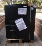
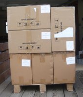
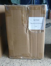
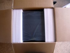
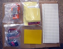
This first batch of photos shows the packaging and parts. The first is as the shipment arrived, the second after removing the shrink wrap. The LiFePO4 cells are shipped in their own boxes, 8 to a box. The Mason case is in its own box, with all of the parts shipped inside the case. The only shipping damage was to the box in the 3rd image. There was a slight crease on the side of the cell behind the damage, which I chose to ignore.


Last edited:


