


You are using an out of date browser. It may not display this or other websites correctly.
You should upgrade or use an alternative browser.
You should upgrade or use an alternative browser.
Careful if you ordered Apexium DIY Box (melted fuse cover)
- Thread starter MartyByrde
- Start date

What was the load pulled from/to the batteries? And were they nuts torqued to spec?
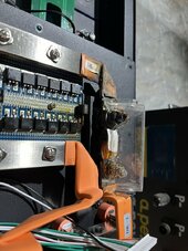
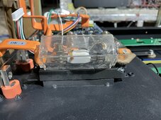
The images shown heat, especially at the input side of the fuse holder. That only occurs if there is resistance, commonly caused by not properly torquing or bad crimps. In this case there are no crimps, so that can be ruled out.
I also seem to see a washer BETWEEN the busbar and the fuse. Thats #1 fail and will create heat for sure.
Nuts/washers are to secure the connection, NOT to be part of the conductive circuit
Imho it does more look like an installer/builder fault (they are DIY kits) and not a mfg risk/failure.

Was there anything mentioned about this in the manual how to assemble the pack? If not so they should include this.
Edit: It seems the same is the case between busbars and the front terminals. That also will heat up. Won't be surprised if the positive terminal (partially) has melted as well.
Can't see it clearly but it does look there is space there as well, indicating maybe a washer there?
Check all connections, also on the negative. There should NOT be any washers between conducting surfaces.

The images shown heat, especially at the input side of the fuse holder. That only occurs if there is resistance, commonly caused by not properly torquing or bad crimps. In this case there are no crimps, so that can be ruled out.
I also seem to see a washer BETWEEN the busbar and the fuse. Thats #1 fail and will create heat for sure.
Nuts/washers are to secure the connection, NOT to be part of the conductive circuit
Imho it does more look like an installer/builder fault (they are DIY kits) and not a mfg risk/failure.
Was there anything mentioned about this in the manual how to assemble the pack? If not so they should include this.
Edit: It seems the same is the case between busbars and the front terminals. That also will heat up. Won't be surprised if the positive terminal (partially) has melted as well.
Can't see it clearly but it does look there is space there as well, indicating maybe a washer there?
Check all connections, also on the negative. There should NOT be any washers between conducting surfaces.
Last edited:
Quattrohead
Solar Wizard
Unfortunately I see a lack of understanding of how to assemble high power electronics.
No washers in the current path, double check all connections including several days after running with load etc.
My battery kits wanted washers in the current path too but mine were copper/brass and I limited them to where absolutely necessary.
There were some height issues with the fuse holder/BMS and bus bars that need to be addressed. Or replace the fuse with a CB.
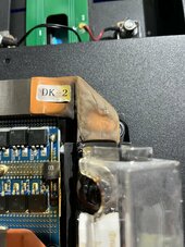
Also, looks like it may have got wet on the front panel and that + connector is toast.
No washers in the current path, double check all connections including several days after running with load etc.
My battery kits wanted washers in the current path too but mine were copper/brass and I limited them to where absolutely necessary.
There were some height issues with the fuse holder/BMS and bus bars that need to be addressed. Or replace the fuse with a CB.
Also, looks like it may have got wet on the front panel and that + connector is toast.
Wow.
Several issues here...
Looks like the bms was bypassed...
Half the current path ignored, and a scary amount of power was being pulled.
I hope OP responds with photos and explanations of the build before failure...
Several issues here...
Looks like the bms was bypassed...
Half the current path ignored, and a scary amount of power was being pulled.
I hope OP responds with photos and explanations of the build before failure...
MartyByrde
Off-Grid Innovator
Daisy is that you?
This box seems unsafe. Perhaps a cash grab, someone’s going to get hurt.

 drive.google.com
It’s only pictures so I had trouble finding the torque specs. I did 60in-lb for the battery nuts.
I’m learning every day and I welcome critiques, but your comments indicate you have not seen the manual. (Or you’re on the payroll like Ray says at the end of his build video.)

I have two more of these battery packs, what needs to be changed on those?

The real question is how do I salvage this to get working tomorrow? Should I just skirt the 400A fuse and hook it straight to the BMS? Seems kind of pointless to have a 400 amp fuse on a 280Ah battery.
This box seems unsafe. Perhaps a cash grab, someone’s going to get hurt.
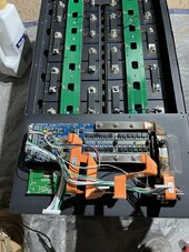
Difficult to say, when exactly this occurred. It seems like it was gradual over time. My system runs just during the day to maximize solar. The three batteries are there to smooth everything out. Between solar and battery it’s between 10 to 30 kW. I installed 224 panels from Santan used 250 W. But one day it just didn’t turn on and I noticed this.What was the load pulled from/to the batteries?
Have you seen the manual?And were they nuts torqued to spec?
Apex DIY Box Assembly Instructions.pdf
drive.google.com
It’s only pictures so I had trouble finding the torque specs. I did 60in-lb for the battery nuts.
I thought that would be tough to spotThe images shown heat, especially at the input side of the fuse holder.
Oh, I was just trying to follow the manualThat only occurs if there is resistance, commonly caused by not properly torquing or bad crimps. In this case there are no crimps, so that can be ruled out.
I also seem to see a washer BETWEEN the busbar and the fuse. Thats #1 fail and will create heat for sure.
Nuts/washers are to secure the connection, NOT to be part of the conductive circuit
can you clarify if you’ve seen the manual?Imho it does more look like an installer/builder fault (they are DIY kits) and not a mfg risk/failure.
I’m learning every day and I welcome critiques, but your comments indicate you have not seen the manual. (Or you’re on the payroll like Ray says at the end of his build video.)
did I misinterpret this photo:View attachment 193476
Was there anything mentioned about this in the manual how to assemble the pack? If not so they should include this.
I have two more of these battery packs, what needs to be changed on those?
There are no washers here nor is this how it was. I loosened these intentionally when I took it apart because the pop on terminal was melted and I needed to use pliers to get it off. I didn’t want to bend this just in case.Edit: It seems the same is the case between busbars and the front terminals. That also will heat up. Won't be surprised if the positive terminal (partially) has melted as well.
Can't see it clearly but it does look there is space there as well, indicating maybe a washer there?
Check all connections, also on the negative. There should NOT be any washers between conducting surfaces.
View attachment 193478
The real question is how do I salvage this to get working tomorrow? Should I just skirt the 400A fuse and hook it straight to the BMS? Seems kind of pointless to have a 400 amp fuse on a 280Ah battery.
Attachments
MartyByrde
Off-Grid Innovator
Gotta take what you can hahaOn an upside looks like that 400a fuse held, lol!
MartyByrde
Off-Grid Innovator
Can you clarify what you are talking about the BMS was bypassed? I built it following the manual. Did I miss something?Wow.
Several issues here...
Looks like the bms was bypassed...
Half the current path ignored, and a scary amount of power was being pulled.
I hope OP responds with photos and explanations of the build before failure...
I'm thankful to see this. I haven't built yet, but was looking at that Apexium, and now I'm getting the benefit of learning more from others' mistakes. So thank you for posting this! I may not have made this mistake, but I might have, too, as I wasn't realizing the importance of keeping washers out of the current path.
MartyByrde
Off-Grid Innovator
Yeah, be careful with the manual.I'm thankful to see this. I haven't built yet, but was looking at that Apexium, and now I'm getting the benefit of learning more from others' mistakes. So thank you for posting this! I may not have made this mistake, but I might have, too, as I wasn't realizing the importance of keeping washers out of the current path.
I think I would have followed that photo the same as you did. It does appear to have an in-current-path washer on each side of that connection, and I would have thought, looking at the photo, that the washer was suggested there to raise the bar above the level of the adjacent insulating material. Obviously, if the bar managed to pinch some of that insulation, it would not make a good connection. But that insulation may be just past the ends of the bar...I'm not sure how well the graphic portrays the actual setup.did I misinterpret this photo:
MartyByrde
Off-Grid Innovator
I’m learning and that’s something that if it’s shown in the manual, I’m going to duplicate it. Glad to know that now thank you.Unfortunately I see a lack of understanding of how to assemble high power electronics.
No washers in the current path, double check all connections including several days after running with load etc.
My battery kits wanted washers in the current path too but mine were copper/brass and I limited them to where absolutely necessary.
There were some height issues with the fuse holder/BMS and bus bars that need to be addressed. Or replace the fuse with a CB.
Also, looks like it may have got wet on the front panel and that + connector is toast.
I haven't seen the manual, I only made conclusions based on the images you've provided.
I agree the images you posted DO look there is a washer between the busbar and the fuse, which is wrong, unless they are 100% conductive like copper.
I'll check the manual (getting curious now) later this evening (its 3pm over here), since it seems there are mistakes in the manuals. I think Apex should improve/correct that off course since they will pose a high risk when pulling massive amps.
Can't blame for that since it seems to be wrong in the manual in the first place, which is only Apex to blame. If you're not familar with high currents, its not that uncommon to follow a manual (which is better than just doing something!)
And sorry for beeing too harsh, since you HAVE used the manual, only that one includes wrong information! Too bad you need to have this close call to find out.
Lt.Dan
Solar Wizard

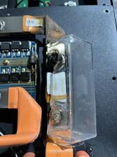
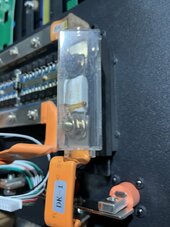
Whether it's in the manual or not, this picture that was posted above needs to be addressed as well, the bus bar needs to go to the top of this copper bus bar, not the Zinc-Plated Steel PEM nut. I saw this when assembling my 3x Seplos cases and it's very easy to make this mistake.
I assembled 3x of the Seplos cases (which are exactly the same) and didn't have manual, so I haven't read it either.
MartyByrde
Off-Grid Innovator
Let us know if you see anything else if you do review the manual. I have two additional batteries and I want to fix. Which ones were you saying to remove?I haven't seen the manual, I only made conclusions based on the images you've provided.
I agree the images you posted DO look there is a washer between the busbar and the fuse, which is wrong, unless they are 100% conductive like copper.
I'll check the manual (getting curious now) later this evening (its 3pm over here), since it seems there are mistakes in the manuals. I think Apex should improve/correct that off course since they will pose a high risk when pulling massive amps.
Can't blame for that since it seems to be wrong in the manual in the first place, which is only Apex to blame. If you're not familar with high currents, its not that uncommon to follow a manual (which is better than just doing something!)
And sorry for beeing too harsh, since you HAVE used the manual, only that one includes wrong information! Too bad you need to have this close call to find out.

Couldn't resist looking into the manual and I agree with the note from @Lt.Dan about the terminals.
The manual is, imho, wrong here. To me, the busbars should make direct contact to the terminals busbar, and the current should NOT be passing the (fixed) nut. That nut/thread is only to secure the bolt.
That busbar should be mounted exactly the other way, so the bar from the fuse makes direct contact with the busbar towards the terminals.
NOT as in this image where the supporting nut is part of the circuit.


I found a picture in another Apexium thread:
This is how it should be in my opinion, not as in the manual

As for the washers: Remove washer C. So the fuse is in direct contact with the busbar. The washers on both sides should 'sandwich' the busbar/fuse, but not be in beween.
Current is passing the main circuit, busbar on busbar / terminal / fuse. Bolts/nuts/washers are to secure it in place. If there is no other way, use suitable conductive materials. Regular (steel/rvs) washers eg aren't.
When in doubt (And I personally always do on high current installs), run it for 15-30min and check with a flir camera. Any bad connection/resistance will show up very clearly.
The manual is, imho, wrong here. To me, the busbars should make direct contact to the terminals busbar, and the current should NOT be passing the (fixed) nut. That nut/thread is only to secure the bolt.
That busbar should be mounted exactly the other way, so the bar from the fuse makes direct contact with the busbar towards the terminals.
NOT as in this image where the supporting nut is part of the circuit.
I found a picture in another Apexium thread:
This is how it should be in my opinion, not as in the manual
As for the washers: Remove washer C. So the fuse is in direct contact with the busbar. The washers on both sides should 'sandwich' the busbar/fuse, but not be in beween.
Current is passing the main circuit, busbar on busbar / terminal / fuse. Bolts/nuts/washers are to secure it in place. If there is no other way, use suitable conductive materials. Regular (steel/rvs) washers eg aren't.
When in doubt (And I personally always do on high current installs), run it for 15-30min and check with a flir camera. Any bad connection/resistance will show up very clearly.
Last edited:
Lt.Dan
Solar Wizard
Yes, the fixed nut is called a PEM nut typically, made by PEM technologies. I used them daily at work. These ones are Zinc Plated Steel, and definitely NOT good for conductivity.Couldn't resist looking into the manual and I agree with @Lt.Dan note about the terminals.
The manual is, imho, wrong here. To me, the busbars should make direct contact to the terminals busbar, and the current should NOT be passing the (fixed) nut. That nut/thread is only to secure the bolt.
That busbar should be mounted exactly the other way, so the bar from the fuse makes direct contact with the busbar towards the terminals.
NOT as in this image where the supporting nut is part of the circuit.
View attachment 193505View attachment 193507
As for the washers: Remove washer C. So the fuse is in direct contact with the busbar. The washers on both sides should 'sandwich' the busbar/fuse, but not be in beween.
I'm quite certain he means for the one labeled "C" in your image to be removed. You want the increased surface area of the contact between the bars, without the added resistance of the washer itself, which is not designed to be an especially good conductor.Which ones were you saying to remove?
MartyByrde
Off-Grid Innovator
So the female wire terminal was melted to the male. I had to snap it off with pliers and I didn’t want to risk bending this metal inside. Can you see this photo for how it looks tightened and if correct?View attachment 193501
Whether it's in the manual or not, this picture that was posted above needs to be addressed as well, the bus bar needs to go to the top of this copper bus bar, not the Zinc-Plated Steel PEM nut. I saw this when assembling my 3x Seplos cases and it's very easy to make this mistake.
I assembled 3x of the Seplos cases (which are exactly the same) and didn't have manual, so I haven't read it either.

Docan’s engineer said I could remove the male plug and put a crimped 2/0 through the hole to attach to this busbar. With the 400A fuse being above the 250A battery disconnect I have installed, can I move all of the DK-1 busbar and connect it here:

I think the busbar only has gotten very hot. Carefully clean, (very) gentle sand the contacts and if preferred renew heatshrink.
I would try replacing the fuseholder and positive terminals (You can buy them separate, if I remember correctly they are Futronics connectors), or you can replace them with 'regular' M8 pass-through connectors. ( https://www.aliexpress.us/item/1005005925179734.html for example)
I would try replacing the fuseholder and positive terminals (You can buy them separate, if I remember correctly they are Futronics connectors), or you can replace them with 'regular' M8 pass-through connectors. ( https://www.aliexpress.us/item/1005005925179734.html for example)
Last edited:
Similar threads
- Replies
- 24
- Views
- 2K
- Replies
- 10
- Views
- 626