diy solar

diy solar

1 awg battery cables that turned out to be 4 awg.

A lot of people dont realize that you can safely solder onto the tops or bottoms of 18650 batteries, either soldering banks together or simply making flat tops into button top cells. Use a real hot iron, 25-40 watts. Clean it and tighten the tip screws. You have about 3 seconds to get on and then get off, and Ive gone as far as having a small glass of water to douse it to cool it as fast as possible. Compressed air may work too.
 
Last edited:
This thread seems like a good place to admit that i had a largeish collection of automotive jumper cables that have mostly been repurposed into my solar system (with crimped ring terminal ends).

I even have some copper clad aluminum (not my fave but they were the only 25ft cables i had) in my 12v system. There is also rebar and gas pipe in my 12v system as conductors, so CCA is sorta high brow in that context. ??
We all use what we got but its accepted that when engaging in seat of the pants engineering with high current DC energy storage equipment, there is a high cost to be paid when we get it wrong. Especially when there are loved ones involved. I recommend scanning equipment with a thermal camera on a regular basis, while pushing up current delivery. Particularly mobile setups.
 
Most of my heavy wiring is done using car battery cables. There are long runs of heavy cable when the battery is mounted in the trunk.
 
We all use what we got but its accepted that when engaging in seat of the pants engineering with high current DC energy storage equipment, there is a high cost to be paid when we get it wrong. Especially when there are loved ones involved. I recommend scanning equipment with a thermal camera on a regular basis, while pushing up current delivery. Particularly mobile setups.

Cant disagree in the slightest. I don't recommend anyone follow in my footsteps, but generally i've been using my hand as the thermal sensing equipment on the 12-48v systems (after 'finding' and getting rid of pesky higher voltage AC on said circuits!!), with some consideration for avoiding the completion of a human circuit. I come from an automotive background, teach basic electrical courses, even have a certification for hybrid and electric vehicles, but i admit that messing with solar/battery setups has made me far more conscientious about the quality of CRIMPS. On a non-hybrid/ev car the only high-current circuits are the starter and alternator and the starter has such a short duration that its wiring is 'undersized' from the factory and only a truly terrible connection will cause a heat-related failure (melted lead battery terminal, for instance). On the alternator the duty cycle is much higher and heat-related damage is more likely, but still rare enough that almost no alternators are out there pushing current through hand-made terminations. Most are still going through factory-built original wiring. So I've had to improve my abilities to crimp a high-current connection, for sure. One of the things i've learned is the value of dielectric grease as a conductor.. of heat! Not so much for bolted ring terminals, but inside plastic connector bodies i've found that it helps the connection disperse heat much better so that it never reaches a damaging temp. An IDEAL connection wouldn't get hot in the first place, but I've got a LOT of used solar panels with MC4s that have sat open to the elements for long periods, and i've found dielectric to increase the reliability of those connections considerably. Short of replacing all old MC4s, i am still brainstorming an effective way to 'wire brush' those connections without disassembling every one..

That said, im still mostly doing it with a large hand-help cable ferrule crimper, not exactly a terminal crimper! Looks like this:
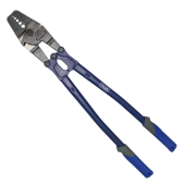
1703001675280.png
It doesn't go up to a large enough size to do anything bigger than about a 0 or 2/0 (i forget now) but while i have some 4/0 in my 48v system, it was all pre-terminated. I have not had to make a 4/0 termination so far and don't have equipment to do one nicely...yet.

Most of my heavy wiring is done using car battery cables. There are long runs of heavy cable when the battery is mounted in the trunk.
From what I have seen they are usually 2/0! One funny thing is opening the trunk of some of those cars and seeing a 2/0 positive wire and what looks like an 8ga or 6ga ground lead going to the body (chassis ground). Sort of relates to why i have rebar and gas pipe in my 12v system. I have heard that copper is something like 15x better as a conductor than iron. One way of interpreting that is just to use 15x more iron than you would have used copper! The case of the 'tiny ground wire' on those chassis grounded rear-battery vehicles is analogous, because 1ft of 6ga followed by 12ft of ENTIRE CAR is essentially as good or better a conductor than the 13ft of 2/0 because there is way more than 15x as much iron/steel as there is copper in the 2/0. There is so much metal that essentially the chassis acts like 'free wire length' and you are only comparing the resistance of 1ft of 6ga vs 13ft of 2/0.

I have a long (~40ft) pair of 'bus bars' made of rebar and black pipe to which i flux-core mig welded some small stainless bolts which have sets of leads going to 2 rows of parked vehicles' 12v batteries, about 5 vehicles per side and with a bunch of 'loose' 12v FLAs sitting on the ground hooked to it as well. This is essentially a large 'battery maintainer' system run by an 80a 12v aio inverter, but it also serves as 'backup power' if needed. It can flow about 50a without too much voltage drop, which when split (unevenly..) between a bunch of batteries is still a pretty small current and no objectionable heat is generated in any one location. It is ~40ft of rebar and gas pipe, hooked to 25' of 2ga CCA, to 4ft of 4ga, to 6" of 6ga into the AIO. :ROFLMAO:
 
Why would you need to fill the "cup" with solder first? Dont you know the solder flows to wherever you apply the heat? I would prefer not to to be sticking the cable into a pool of burning hot liquid, especially if its a tight fit. And you cant crimp it first that way.
And that leaves the cable and its insulation uphill in the heat flow. Most welding cable might be okay with that. If its PVC jacketed bye bye insulation.
Lots of ways to do this. I prefer the way the navy trained us in avionics school back in 1980.
Crimp the terminal onto the wire. Put it in a vise or similar securing tool with the terminal up and the cable down. Heat the top of the terminal first. Then slowly bring the heat down until the solder flows into the bottom of the terminal. Keep the majority of the heat at the top. The solder will defy gravity and flow upwards as long as the heat is applied there. Do not apply too much solder or it flows down the cable. (Which isnt the end of the world but makes the cable inflexible and that can be an issue) Once the solder is cool enough to harden you can apply a soaking wet towel to it to speed up handling time if youre doing a lot of joints. Do not move it until it cools enough to harden.
The soaking wet towel is also handy to have around for safety.
A hard fast rule of soldering is its better to use a lot of heat and get out fast than it is to dick around with a too small iron or torch heating up everything around it. And heat sinks work.

Clear we differ in opinion on how to do it.

By filling the cup and having the solder liquid when the welding cable hit it the heat transters to the wire and the solder wicks up into it. The cup needs quite a bit of solder or the whole thing goes cold when you put the wire in. Once you figure out the timing it is repeatable and the jacket isn't harmed.

I got good results with it the few times I did it prior to having the temco hydraulic crimper.

I was an AT2 when I got out and did go to solder school and get my card and multi-level board repair stamp. Not quite the same thing as large cables, but most of it applies. My A school in 1989, at millington TN, didn't cover solder at all. We got a quick 1 day course in AFTA. My solder training was done in Lemoore, two weeks of TAD to the school and it was tough to pass the advanced course.

Were I doing it that way I would dip the wire in paste flux and insert it into the cup. Then heat the bottom of the cup and apply solder until it flowed to fill the wire and cup with a meniscus. The wire strands would be clearly visible through the solder. The problem is when I did it that way then cut it apart the solder was only about half through the wire and I damaged the sheath a bit. Doing it the way I described the solder was all through the wire.


Note: I do use a MAPP gas torch for this since a simple propane is under powered for the job.

All that said, I see no reason to solder the lug if a hydraulic crimper is used and results in a cold weld.
 
Last edited:
Clear we differ in opinion on how to do it.

By filling the cup and having the solder liquid when the welding cable hit it the heat transters to the wire and the solder wicks up into it. The cup needs quite a bit of solder or the whole thing goes cold when you put the wire in. Once you figure out the timing it is repeatable and the jacket isn't harmed.

I got good results with it the few times I did it prior to having the temco hydraulic crimper.

I was an AT2 when I got out and did go to solder school and get my card and multi-level board repair stamp. Not quite the same thing as large cables, but most of it applies. My A school in 1989, at millington TN, didn't cover solder at all. We got a quick 1 day course in AFTA. My solder training was done in Lemoore, two weeks of TAD to the school and it was tough to pass the advanced course.

Were I doing it that way I would dip the wire in paste flux and insert it into the cup. Then heat the bottom of the cup and apply solder until it flowed to fill the wire and cup with a meniscus. The wire strands would be clearly visible through the solder. The problem is when I did it that way then cut it apart the solder was only about half through the wire and I damaged the sheath a bit. Doing it the way I described the solder was all through the wire.


Note: I do use a MAPP gas tourch for this since a simple propane is under powered for the job.

All that said, I see no reason to solder the lug if a hydraulic crimper is used and results in a cold weld.
I was an AQ3. Same A school as you, AFUN/P and BE&E too right? Millington was a blast. After that I went to NAS Oceana for F-4 FRAMP. Then VF-21 Miramar/CV-43.
 
I had calibration school in NAS North Island after millington then off to Lemoore to work in the calibration lab there for 2.5 years. After that I was off to Corry station to do school for working on EP-3 systems with orders to VQ-1 in Guam but got and ordmod to go to VQ-5 instead. Spent 2.5 years there working on ES3-A aircraft.

Spent 6 years in because of the AFTA and crow at the end of A school. Knew at 2 years it wasnt a career for me but I learned a ton about a lot of stuff while in. And had a lot of fun.
 
@Batvette @robbob2112
you should be very thankful for those schools. these days i watch a young sailors enter the fleet with absolutely no skills as they teach them via online presentations (total hogwash IMHO).
I went through several navy and Marine Corps courses while I was in (80's) but none of them were electrical oriented and they have stood me through for years.
I have several friends who went into the navy and Marine Corps as Electricians, and Electronics repair and the schools they got in the 80's were the cats meow. the soldering course from what one friend described sounds like a mental torture test.. things like prescribed amount of solder and the ways they tested their soldered joints sounds truly fiendish.

all that to say just be glad for what you got as they no longer teach like that.
 
also to comment on suppliers, I found Temco several years ago and they are my goto as well. shipping to japan has been reasonable and yes the one drawback is the way they roll the cable. the end of it is always a PITA to straighten out. but i got into the habit of buying a couple of feet longer then my anticipated needs after mismeasureing one time and coming up short. so these days I usually end up just cutting off a couple of feet and selling it to the recyclers here locally and getting back almost what I paid for it (minus shipping).

FWIW I use an old Navy/USMC Cable crimper that one of the airwings tossed when they were having an tool inspection.
For the uninitiated, they are allowed XX tools on their roster, any excess is a killer hit on the inspection as all tools must be accounted for to avoid leaving a tool lying about and having it sucked into a jet turbine engine.

This thing crimps from 004 stainless cables down to 4gauge copper and anything in-between. you have to clamp it in a vice to use though as the handles are so long. i think its primary use was for the redundent wire cables for control surfaces that were backups for the hydraulics.
 
I suppose those also are abandoned to the dustbin of history?

(Just imagine using F35 for close air support and losing hydraulics.)
Sir,

not sure... I currently do ships repair for a living at Yokosuka Naval base, just something i pulled out of a trash bin at NAS Atsugi years ago and a friend who worked airframes identified it for me.
 
I never dealt with the planes. I did support missiles on subs.

But of course I was referring to a particular flight of fancy:

 
I never dealt with the planes. I did support missiles on subs.

But of course I was referring to a particular flight of fancy:

I am not surprised.. just look at the LCS class ships. less than ten years old and they are already planning on decommissioning them.
 
Earlier in this thread I had mentioned I was buying my cables from Windy Nation. Since then, I've ordered a lot of cable from AC-DC Wire and Supply on ebay. The quality and shipping speed have been excellent!
 
I did enjoy my schools, and you are right, the solder school was the hardest to pass. They inspected most of my joints with a microscope. They would point out one little pit on an otherwise perfect joint and reject it. Send me back to remove all the components and put them back again. That was what we started with, a board with about 50 components through the hole in the board style. We had to do a day of class watching and learning, then go practice by removing the components without lifting the runs from the board. inspect/reinstall. Several times of that and then more class for surface mount stuff and using the microscope to work. Then the same with a different board. Then a final project that was pass/fail and if you failed you got 2 more tries and if you failed those you were washed out. After that they picked 3 of us out of a class of 10 to go on and do the multilevel board repair which was actually less torturous as far as grading went but far more intense as far as the learning went.
 
Back
Top